
Specifications


25
7.4 OUTPUT CODE DESCRIPTIONS
2331 “NORMAL RELAY ACTIVATE (GAS ALARM)”: This menu item is used to select the type of alarms which will activate each relay.
There are 3 choices in this menu item; “Sense”, “All” or “None”. In the “Sense” mode, any channel listed in menu item 2112, which goes into
alarm, will cause a specific relay to activate. The maximum number of channels that can be associated with any one relay is 32. In the “All”
mode, any channel that is in alarm will cause a specific relay to activate. In the “None” mode, no channel alarms will activate a specific relay.
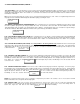
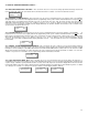
To achieve this, enter “2331” and the display will look like the box below. Use the “1” or “3” button to scroll down or up through the choices
then push the “2” button to scroll to the next relay and eventually out of this menu code function. If you are not configuring all the relays, use
the “2” button to scroll to the end of this menu and the display will indicate “Finished”.
2112
“SETTING GAS ALARM CHANNELS FOR RELAY MONITORING”: In this menu item the user can select the channel(s) which
will be monitored for gas alarm conditions for each relay. Any channel included in this list, which goes into gas alarm will cause a specific
relay to activate as long as the menu item “2331” has been set to “Sense”. The maximum number of channels that can be associated with
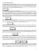
any one relay is 32. The choices are from 1 to 128 or “none”. To achieve this, enter “2112” and the display will look like the box below. The
first number displayed indicates the first channel on the monitored list for that relay. Pressing “2” repeatedly allows the user to view which
channels are listed for monitoring by each relay. When the display indicates “done”, this means you are at the end of the list. If you wish to
add more channels, use the button “3” to increment to that channel number. Once you have added all the channels to be associated with that
relay, press button “2” until the display once again indicates “done” then press button ‘2” once more to scroll to the next relay. Repeat this
procedure until all desired channels have been associated with specific relays. At the last relay (8), press button ‘2” to scroll out of the menu
and the display will indicate “Finished”.
2323
“SETTING RELAY GAS ALARM ACTIVATION LEVEL”: This menu item allows the user to select the gas alarm activation level
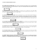
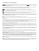
for each relay. The choices are “Low”, “Mid” or “High” gas alarm. To achieve this, enter “2323” and the display will look like the box below.
Use the “1” or “3” button to scroll down or up through the choices then push the “2” button to scroll to the next relay. If you are not configuring
all the relays, use the “2” button to scroll to the end of this menu and the display will indicate “Finished”.
2321 “SETTING RELAY COIL STATE FAIL SAFE”: This menu function sets the relays to “normally energized” or “not normally en-
ergized” state when the circuit is in non-gas-alarm state. Normally energized is what we designate as “Fail-safe”. To achieve this, enter
“2321” and the display will look like the box below. Use the “1” or “3” button to select “No” or “Yes” then push the “2” button to scroll to the
next relay. If you are not configuring all the relays, use the “2” button to scroll to the end of this menu and the display will indicate “Finished”.
2313 “SETTING RELAY COIL LATCHING STATE”: This menu item sets the “ latching” state of a relay. If a relay has been set to
latching, it will not de-energize once the gas or fault alarm condition is removed. The only way to clear the relay is to press and hold the
acknowledge push-button for approximately 7 seconds. To achieve this, enter “2313” and the display will look like the box below. Use the “1”
or “3” button to select “No” or “Yes” then push the “2” button to scroll to the next relay. If you are not configuring all the relays, use the “2”
button to scroll to the end of this menu and the display will indicate “Finished”.
2311 “SETTING RELAY “ON” TIME DELAY VALUE”: This menu function allows the user to select the “ON” time delay (delay on
Make) for each relay on the system. The “ON” delay is the amount of time after an alarm has been initiated until the relay is activated. The
number displayed is in minutes, so 0.1 = 6 seconds. If the alarm goes away before the relay is activated, the relay will not activate. If a
fault alarm is assigned to a specific relay and a fault occurs, the “On” delay has no affect and the relay will be activated immediately. To
achieve this, enter “2311” and the display will look like the box below. Use the “1” or “3” button to scroll down or up through the values then
push the “2” button to scroll to the next relay. If you are not configuring all the relays, use the “2” button to scroll to the end of this menu and
the display will indicate “Finished”. The delay time increments at a rate of 0.1 minutes per step change. Example: 0.6 minutes = 36 seconds.
2312 “SETTING RELAY “OFF” TIME DELAY VALUE”: This menu function allows the user to select the “OFF” time delay (delay on
Break) for each relay on the system. The “OFF” delay is the amount of time the relay stays activated after an alarm is removed. The number
displayed is in minutes, so 0.1 = 6 seconds. The delay is also in effect for fault relay activation. To achieve this, enter “2312” and the display
will look like the box below. Use the “1” or “3” button to scroll down or up through the values then push the “2” button to scroll to the next re-
lay. If you are not configuring all the relays, use the “2” button to scroll to the end of this menu and the display will indicate “Finished”. The
delay time increments at a rate of 0.1 minutes per step change. Example: 0.6 minutes = 36 seconds.
RL 001 Menu 2331
Normal Act Sens
RL 001 Menu 2112
Mon Channel 1
RL 001 Menu 2323
Act Level Low
RL 001 Menu 2313
Latching? No
RL 001 Menu 2321
Fail Safe ? Yes
RL 001 Menu 2311
On Delay 0.0
RL 001 Menu 2312
Off Delay 0.0