
Specifications


19
7.0 SYSTEM PROGRAMMING– GENERAL
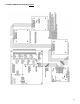
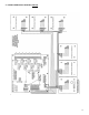
System Configuration: The PDC controller is completely configurable by the end user. Reference the following pages for more details
regarding the configuration of a system.
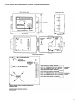
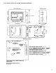
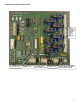
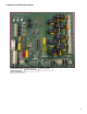
Programming: Any changes in the system operation can be made quickly and easily by means of the push-button programming feature. Three
small, momentary push-buttons can be located on the upper left corner of the circuit board. These push-buttons can be used to enter a large
selection of four digit codes to access a wide range of system functions and features. For more detailed information on system programming,
consult the programming section of this manual.
The PDC controller has an extensive menu system that allows the user maximum flexibility, through programming, to achieve a wide range of
system functions. Important: Please carefully read through the programming section before attempting to make programming changes.
The system menu structure is broken into three major sections. “Input Control”, “Output Control” “Other Codes”. Input control allows the user to
program all the desired parameters for the sensor input channels. Output control allows the user to program all the desired parameters for the
relay outputs for controlling other devices. Other codes provide the user with other functions to customize their system.
The following table indicates available programmable functions and the input codes for each. Detailed descriptions for each function code can
be found on following pages.
NOTE: Holding down a button for more than 2 seconds will allow the user to scroll very quickly.
WARNING: CHANGING PROGRAMMING CODES MAY RESULT IN SYSTEM PROBLEMS. DO NOT ATTEMPT WITHOUT CONSULTING
THE FACTORY.
7.1 SYSTEM PROGRAMMING– INPUT CODES
CODE DESCRIPTION
1211 Low Alarm Set Point
1212 Mid Alarm Set Point
1213 High Alarm Set Point
2211 Low Alarm Ascending / Descending
2212 Mid Alarm Ascending / Descending
2213 High Alarm Ascending / Descending
3211 Channel Enable / Disable NEVER DISABLE ALL CHANNELS
3212 Add new Channels setting all channels ( default sensor CO 200 ppm )
1311 Add new Channels keeping sensor type
3213 Changing Analog Channels 4-20 mA or Volts
1231 Changing sensor type from list of configured sensors ( page 23 )
1223 Setting sensor direction ( common Negative sensors are NO2 and Oxygen )
3312 Zero Mask Number ( used to reduce bounce at Zero reading )
3322 Fault Level Cutoff ( Set fault level for Analog transmitters )
3233 Test Channel Select
1323 Unlock code ( some codes require unlock code before using )
2231 Calibrate High Input Range @ 20 mA A/D ( Analog Channels 1 - 8 )
1221 AutoNull ( DST Electrochemical sensors )
1222 Modify Calibration Gas Concentration ( i.e. 100 ppm CO )
2131 Calibrate Low Input Range @ 4 mA A/D ( Analog Channels 1 - 8 )
2133 Set Low Input Range (NULL Value normally 0 for most sensors )
2233 Set High Input Range ( SPAN Value i.e. 200 ppm CO )