
Specifications


18
6.0 SYSTEM OPERATION
Powering up: Double check wiring connections at both the PDC controller and the remote mounted DST series digital transmitters or
AST series analog transmitters prior to powering up the system. Any system that has been damaged because of incorrect wiring is not cov-
ered under warranty. Important: Ensure “end-of-line” jumpers are installed on any transmitters at the end of a wiring run. Reference photos on
preceding page for location.
Upon power up, the display will indicate the model series and software version number. Example: “PDC128 ver. # 1.29”. The system will
immediately start to scroll through all enabled channels, displaying the channel number, alarm status, gas sensor type, and concentration of
gas being detected at that particular moment.
Fault Conditions: The micro processor initiates a check of all installed transmitters and performs a self-diagnostics. If one or more of the model
DST digital transmitters are not communicating with the main controller, the microprocessor will attempt to communicate with it a number of
times. If communication has not been established after approximately six to ten minutes, the display will indicate a “com error”, example: “CH
001 Com Error CO - 0 ppm”. The display will scroll through all channels and display their individual status, including channels with com errors.
If corrections are made to deal with “com errors”, it will take up to 4-minutes (for 128-channel systems) before any further communication er-
rors are displayed.
The system software has a “watch-dog” designed into it. The watch-dog is designed to monitor the microprocessor for problems. If the watch-
dog detects that the microprocessor has locked up for any reason, it automatically resets it. If the watch dog detects more than three system
resets, on the fourth reset, the display will indicate “System Error”. A system error is designed to let the user know that something is interfering
with the basic operation of the controller.
When a system error has occurred, the auxiliary output (marked “+AUX-”), is activated to provide 24VDC power for an external alarm, if it has
been programmed to do this (code “2121”). A system error can be reset by depressing the acknowledge push-button for seven seconds.
Normal Operation: During normal operation the LCD display scrolls through all enabled channels, pausing for approximately 1.5 seconds per
id number, displaying the channel number, alarm status, gas type and concentration at that moment.
When an alarm condition occurs, the appropriate alarm level LED on the front panel illuminates and any relays programmed to be activated at
the same gas alarm level will de-energize (fail-safe operation) or energize (non fail-safe operation). At high alarm condition, the audible alarm
is also activated. It can be silenced by depressing the acknowledge push-button momentarily. If the user has programmed a time delay, each
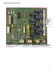
relay will be activated according to the type and duration of delay programmed. The amber colored LEDs located on the main circuit board
just to the left of the bottom relay provide a visual indication of the relay coil status. If the coil is energized, the LED is illuminated.
The PDC circuit design also employs the use of filtering devices, mounted on the board beside the relays. These devices are designed to
capture EMI (electromagnetic interference) and dump it to ground so it does not interfere with the operation of the microprocessor. It will not
stop all EMI but does provide a substantial amount of protection for the main circuit.
If the “strobe” output has been utilized, any 24VDC powered alarm device connected to this terminal strip will be activated by low alarm by
default. If the user prefers this alarm to be activated by another gas alarm level, it can be changed by inputting code “2333” and selecting
“mid” or “high”. This is a universal alarm meaning that any channel in gas alarm will activate it. 12VDC powered alarm devices can also be
utilized by requesting the optional miniature 12VDC output circuit board at the time of ordering.
IMPORTANT NOTE: The current capacity of this output is 400 mA.
Battery Back-Up:
It is recommended that the user purchase an “off-the-shelf” UPS system and use it to provide back up battery power to the system. If the user
decides on this option, the UPS must be connected to the line voltage input terminal strip of the PDC. CETCI has a standard UPS system
available that has been tested with a PDC system.
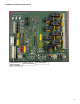
Power Failure: In the event of a system power failure, first check to ensure that the system primary fuse has not “blown”, prior to performing
other trouble-shooting functions (reference system interior photo on page-10). The system primary fuse is located just below the incoming
power terminal strip (upper right side of system enclosure base). The PDC also has two other fuses for secondary protection. One is located
in the switching power supply module underneath the main circuit board. This is a glass, soldered fuse.
The second is an automatic resetting thermal fuse that can be located at the bottom right side of the main circuit board just above the 24VDC
input power terminal. This fuse does not have to be replaced. In the unlikely event that this fuse “blows”, disconnect one of the 24VDC wires
from the switching power supply at the 2-pole wire terminal and allow the thermal fuse about 5 minutes to cool down, then re-connect the wire
(reference system interior photo on page-10). The fuse automatically resets itself after it cools down.
In the event of a power failure, any system relays configured as fail-safe will de-energize and if power is intact at devices controlled by the
system relays, these devices will be operating continuously until system power has been restored.
Trouble-Shooting: Reference the trouble-shooting section of the manual for more details.