Critical Environment Technologies Canada Inc. “PDC” Series Programmable Digital Controllers & “DST” Series Digital Sensor / Transmitters INSTALLATION / OPERATION MANUAL REV: G Feb 01, 2013 Critical Environment Technologies Canada Inc. Unit 145, 7391 Vantage Way Delta, BC V4G 1M3 Canada Ph: 604-940-8741 Fx: 604-940-8745 www.critical-environment.
IMPORTANT NOTICES READ AND UNDERSTAND THIS OPERATION MANUAL PRIOR TO INSTALLING OR USING THIS INSTRUMENT. THE MANUFACTURER IS NOT RESPONSIBLE FOR ERRORS AND PROBLEMS RESULTING FROM THE USE OF THE WRONG TYPE AND GUAGE WIRE/CABLE OR PROGRAMMING CHANGES MADE BY UNTRAINED OR UNAUTORIZED INSTALLERS OR END USERS. THIS EQUIPMENT SHOULD BE INSPECTED AND MAINTAINED BY A QUALIFIED AND TRAINED TECHNICIAN. FOR MORE INFORMATION REFER TO OTHER SECTIONS OF THIS MANUAL.
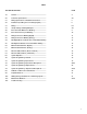
INDEX SECTION DESCRIPTION PAGE 1.0 General ................................................................................... 4 2.0 Controller Specifications ...................................................... 4-5 2.1 Wiring Specifications & Installation Instructions ............... 5 3.0 Installation (including sensor mounting heights) .............. 6 3.1 Wiring ..................................................................................... 6-7 3.
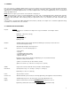
1.0 GENERAL PDC series systems are configurable, digital, microprocessor based, controllers for use in non-hazardous (non-explosion rated) environments for commercial and industrial applications. They are available in several basic configurations. One to eight analog channels, one to sixteen digital channels, one to thirty-two digital channels, one to sixty-four digital channels, one to ninety-six digital channels, one to one hundred and twenty-eight digital channels.
2.0 CONTROLLER SPECIFICATIONS, CONT’D….. Fuses: Replaceable: Primary: 1.5 amp, Power supply: 2.0 amp Options: a) BACnet Output Module b)Remote mounted 4” diameter strobe light c) Remote mounted combination strobe light/siren alarm d) Remote mounted 5” industrial horn (115VAC) e) Water/dust tight, corrosion resistant system enclosure f) Remote relay module g) Remote analog output module h) Remote annunciator (remote display) i) Remote power supply 2.
3.0 INSTALLATION Standard: Four 3/16” diameter mounting holes can be located at the corners inside the enclosure base. Take caution when using installing tools inside system enclosure to avoid damaging internal components. Water/dust tight: These enclosures are optional and are supplied with four mounting feet that must be attached by the installer. A liquid tight conduit fitting must be used to maintain the water tight state of this enclosure.
3.1 WIRING Digital System: If a digital system has been selected, refer to “WIRING SPECIFICATIONS AND INSTALLATION INSTRUCTIONS” on page 5. The wiring terminal strip for the digital system can be found at the bottom middle edge of the circuit board. Refer to section 4.1, page-10 for a detailed wiring drawing. NOTE-1: Do not use solid-core wire at circuit board terminals. Solid-core wire has memory and can tear a soldered terminal right off the circuit board. This is not covered under warranty.
3.2 JUMPER SETTINGS AND WIRING EXAMPLES, CONT’D….. System wiring can originate at the “CAN-IN” or “CAN-OUT” wiring terminals of the PDC. They are parallel connected internally. System wiring can also originate at both and run in two directions to save on conduit and wire. Several installation examples are described below with correct jumper positions indicated. See the page-12 for diagram layouts to match the examples described below.
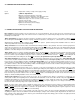
4.0 ENCLOSURE OUTER DIMENSIONS KNOCKOUTS KNOCKOUTS 12.25” 311 mm KEY LOCK SILENCE PUSH-BUTTON 4.19”” 106 mm AUDIBLE ALARM 12.25” 311 mm NOTE-1: Three knockouts can be found along the top edge and three along the bottom edge of the system enclosure NOTE-2: Standard enclosure is powder painted, 18-gauge steel with locking, hinged door. Optional water/dust tight, corrosion resistant enclosures for harsher environments are available. Consult your local authorized distributor for more details.
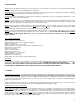
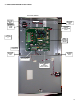
4.1 ENCLOSURE INTERIOR LAYOUT PHOTO RELAY WIRING TERMINALS ENCLOSURE MOUNTING HOLE MAIN FUSE ENCLOSURE MOUNTING HOLE INCOMING LINE VOLTAGE SYSTEM POWER 24VDC FROM INTERNAL SWITCHING POWER SUPPLY TOP OF ENCLOSURE >>> WIRING TERMINALS FOR DIGITAL SENSORS PROGRAMMING PUSH-BUTTONS ENCLOSURE MOUNTING HOLE ENCLOSURE MOUNTING HOLE WIRING TERMINALS FOR STROBE, ETC.
4.
4.
4.
4.
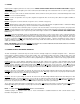
5.0 MAIN CIRCUIT BOARD PHOTO DIGITAL DRY CONTACT RELAYS FOR CONTROL OF EXTERNAL DEVICES SUCH AS FAN STARTERS, ETC.
5.
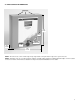
5.2 DST CIRCUIT BOARD PHOTO (ELECTROCHEMICAL) LINK LED AUTO-CAL PUSH-BUTTON AUTOMATIC RESETTING THERMAL FUSE LED-2 FOR CALIBRATION WIRING INPUT TERMINALS ELECTROCHEMICAL SENSOR SOCKETS WIRING OUTPUT TERMINALS ATTACH METER LEADS HERE TO VIEW SENSOR RESPONSE, IF DESIRED END-OF-LINE JUMPER GOES HERE 5.
6.0 SYSTEM OPERATION Powering up: Double check wiring connections at both the PDC controller and the remote mounted DST series digital transmitters or AST series analog transmitters prior to powering up the system. Any system that has been damaged because of incorrect wiring is not covered under warranty. Important: Ensure “end-of-line” jumpers are installed on any transmitters at the end of a wiring run. Reference photos on preceding page for location.
7.0 SYSTEM PROGRAMMING– GENERAL System Configuration: The PDC controller is completely configurable by the end user. Reference the following pages for more details regarding the configuration of a system. Programming: Any changes in the system operation can be made quickly and easily by means of the push-button programming feature. Three small, momentary push-buttons can be located on the upper left corner of the circuit board.
7.2 INPUT CODE DESCRIPTIONS 1211 “LOW ALARM SET POINT”: This code allows the user to set or change the system low alarm set point. This is the point at which the low alarm LED illuminates and any relays designated as “LOW” are de-energized. To achieve this, enter code “1211” and the LCD indicates the channel number (it always starts at channel-1), the menu number you just entered and the existing low alarm set point. Use the button “1” to decrement this value or button “3” to increment this value.
7.2 INPUT CODE DESCRIPTIONS, CONT’D….. 3212 “ INPUT ADDRESS”: This code is used to initiate and configure the system. First ensure all external devices such as DST transmitters, CAN network bridges, external relay boards or external analog output boards are installed and wired. To achieve this, enter “3212” and the display will look like the box below. Use the “1” or “3” button to scroll down or up to set the desired ID code number then push the “2” button to scroll to the next channel.
7.2 INPUT CODE DESCRIPTIONS, CONT’D….. 1221 “AUTO NULL”: This code allows the user to force the remote DST (digital signal transmitter) to null and reset to zero with clean air flowing. To achieve this, enter code “1221”and the LCD indicates “Channel-1, Menu 1221 and Auto Null”. Press button “2” to accept this and the LCD briefly indicates “NULL”. Press button “3” to scroll to the next channel, if more than one channel has been enabled. If not, the LCD indicates “\Finished”.
7.2 INPUT CODE DESCRIPTIONS, CONT’D….. GAS SENSOPR TYPE - CODE 1231 - GAS SENSOR LISTING DISPLAY INDICATION GAS TYPE SENSOR TYPE UNITS OF MEASURE CO el 200 ppm C3H8 ss 50 %LEL C3H8 ct 100 %LEL CH4 ss 50 %LEL CH4 ct 100 %LEL NO2 el 10.0 ppm CL2 el 5.0 ppm CL2 el 20.0 ppm NH3 el 500 ppm O2 el 25.0 %Vol O2 ga 100.0 %Vol O3 el 2.00 ppm O3 el 1.00 ppm CO2 ir 2000 ppm CO2 ir 5000 ppm CO2 ir 5.0 %Vol CO2 ir 20.0 %Vol CO2 ir 100.
7.
7.4 OUTPUT CODE DESCRIPTIONS 2331 “NORMAL RELAY ACTIVATE (GAS ALARM)”: This menu item is used to select the type of alarms which will activate each relay. There are 3 choices in this menu item; “Sense”, “All” or “None”. In the “Sense” mode, any channel listed in menu item 2112, which goes into alarm, will cause a specific relay to activate. The maximum number of channels that can be associated with any one relay is 32. In the “All” mode, any channel that is in alarm will cause a specific relay to activate.
7.4 OUTPUT CODE DESCRIPTIONS, CONT’D….. 3221 “RELAY ENABLE / DISABLE”: This code allows the user to enable or disable a specific relay. The choices are “ Yes” or “ No” . To achieve this, enter “3221” and the display will look like the box below. Use the “1” or “3” button to select ‘No” or “Yes” then push the “2” button to scroll to the next relay. If you are not configuring all the relays, use the “2” button to scroll to the end of this menu and the display will indicate “Finished”.
7.4 OUTPUT CODE DESCRIPTIONS, CONT’D….. 2333 “STROBE OUTPUT ACTIVATION LEVEL”: This code controls the gas alarm level at which the “ strobe” output (24VDC @ 400 mA maximum) is activated (upper left side of main board). The choices are a universal Low, Mid or High gas alarm. To achieve this, input code ‘2333” and the display will look like the box below. Use button “1” or button ‘3” to scroll through the selections then push button “2” to accept the change. The LCD indicates “Wait”.
7.4 OUTPUT CODE DESCRIPTIONS, CONT’D….. 3232 “REMOTE ANALOG OUTPUT ADDRESS INITIALIZATION”: This code allows the user to add remote analog output module(s) to a PDC system by setting the digital ID (address) so the PDC will recognize it. The device must be installed, wired and powered up to accomplish this. To achieve this, input code “3232” and the LCD will look like the box below.
7.4 OUTPUT CODE DESCRIPTIONS, CONT’D….. 3332 “MESSURE ANALOG INPUT VOLTAGES”: This code allows the user to measure the analog input without having a external volt meter To achieve this, input code “3332” and the LCD looks like the box below. Use button “3” to increment channels to monitor. CH 001 Menu 3332 Voltmeter 0.01 3123 “INITIALIZE SYSTEM DEFAULTS”: This menu item resets the system configuration back to the original setup.
8.0 CALIBRATION OF SENSOR / TRANSMITTERS Frequency: All sensors require regular calibration maintenance to ensure accuracy and indeed to confirm that they have not expired. Electrochemical sensors installed in applications such as parking facilities should be gas calibrated a minimum of once per year. A frequency of once every six months is preferred. Sensors installed in applications that must specially meet the need for Occupational Health & Safety standards should be gas calibrated once every six months.
9.0 PERIPHERAL DEVICES Extra Relays: If the target application will require more than eight relay contacts, optional remote relay modules (M/N RRM-8) can be purchased and attached to the system wiring run. Each module provides eight only S.P.D.T. dry contact relays rated 5 amps @ 240 VAC. The extra relays can be programmed from the system codes. The RRM-8 can be remotely installed and wired directly into the BUS wiring. It receives it’s power from the PDC.
12.0 TROUBLE-SHOOTING If after 10 min of operation there are errors in the system the following check list should be carried out. 1) Check that there is adequate power on the system. a) 120VAC (main control board) b) 24VDC line on the system wiring run (at each DST) 2) Check that all the link (amber) lights are “on” (DST’s and other external circuit boards). 3) Check that there are no open loops on the analog inputs (analog systems only).
12.0 TROUBLE-SHOOTING, CONT’D….. With the POWER ON 1) Check the voltage on the 24VDC line. A reading of anywhere between 24.0 VDC to 20.0VDC is acceptable. Anything below 20.0 VDC is unacceptable. 2) Set the controller into 3323 mode Check the voltage between the data-A line and COM. This should be roughly 2.5 volts. Check this voltage at both ends of the node. A reading of anywhere between 2.0 VDC to 3.0VDC is acceptable. Check the voltage between the data-B line and COM. This should be roughly 2.5 volts.
12.0 TROUBLE-SHOOTING, CONT’D….. Software 1) Check System Error/WDT Test Menu 3331. The display will indicate what the source of the error is then a number. Next it will ask if you wish to test the WDT. 2) Stack Overflow – Software error call factory 3) Stack Underflow– Software error call factory 4) Brown Out – There has been a problem with the power. Check power. 5) Watch dog time out. The unit has encountered a software problem call factory 6) External relay board problem.