
Installation guide
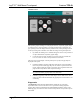
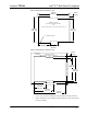
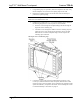
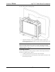
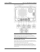
Table Of Contents

Isys
®
5.7” Wall Mount Touchpanel Crestron TPS-6L
3. Using masking tape (or equivalent), fasten the template to the wall; verify
that the template is level, and trace the opening shape on the wall.
4. Remove the template, and then cut out and remove the traced shape to
produce the required opening.
NOTE: Before inserting the TPS-6L in the mounting hole, ensure that all required
cables have been installed in the wall.
5. Install the four supplied #6 x 2-½” screws and mounting clips as shown in
the following diagram (two on the top and two on the bottom).
• Insert the screws through the touchpanel flange and then through the
larger hole in the mounting clip.
• Thread the screws through the smaller hole in the mounting clips and
tighten the screws only enough that the mounting clips are brought
flush with the rear of the touchpanel flange. Do not compress the
mounting clips at this time.
Attaching the Screws and Mounting Clips
6. Connect the Cresnet cable, using the supplied mating connector, to the
Cresnet port; attach the Ethernet cable, if required; attach all other cables
(audio and video); and, if included, connect and attach the optional external
speaker kit (SPK-6L); and position the TPS-6L in the mounting hole. Refer
to “Hardware Hookup” which starts on page 34.
32 • Isys
®
5.7” Wall Mount Touchpanel: TPS-6L Operations & Installation Guide - DOC. 6630A