
Specifications
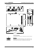


Crestron QM-RMCRX QuickMedia Receiver/Processor
VIDEO
Composite Video
One BNC type connector for composite video output.
NOTE: Composite video is a type of video signal in which all of the video
information, the red, green, and blue (horizontal and vertical sync) signals are
mixed together.
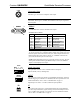
RGBHV
1
10
15
RGBHV
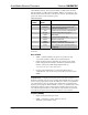
One DB15HD male connector for RGB video output.
DB15HD Connector Pinout
PIN DESCRIPTION PIN DESCRIPTION
1 Red Signal 9 N/C
2 Green Signal 10 Sync Ground
3 Blue Signal 11 ID0 (Ground)
4 Reserved 12 ID1 (No Connection)
5 Ground 13 Horizontal Sync
6 Red Ground 14 Vertical Sync
7 Green Ground 15 No Connection
8 Blue Ground
NOTE: RGB is a computer signal that uses the standard High Density (HD-
15) 15-pin connector. It is comprised of three analog video signals: red, green,
blue and separate horizontal and vertical syncs. Most computer monitors use
RGB (usually called VGA, SVGA, XVGA, etc.). RGBHV consists of red,
green, blue, horizontal sync and vertical sync.
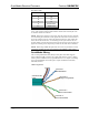
NOTE: Some DLP display devices are extremely sensitive to noise. The anti-
aliasing filter included with the QM-RMCRX may be used at the RGBHV
output or on the display device input.
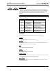
AUDIO
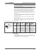
SPCH L R
S G S G S G
Audio Line Level
One 6-pin mini connector. Three unbalanced line level outputs:
Speech (SPCH), Left (L) and Right (R).
INPUT
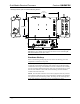
1 2 3 4 G
INPUT
This connector provides four software programmable digital inputs. Inputs are
Schmidt trigger type (nominal 2.5 V threshold) with 24 V input tolerance. For
detailed information, refer to “Slot 2: C2I-RMC-DI4” on page 37.
Digital inputs are rated 0 – 24 VDC, 20K ohms input impedance.
IR
S G
IR
A 2-position mini-connector is a mini-implementation of a single PRO2 IR
port. The output is labeled S (signal) and G (ground). Infrared output is rated
up to 1.2 MHz. Serial protocol is one-way RS-232. For detailed information,
refer to “Slot 1: C2I-RMC-IR1” on page 37.
Operations Guide – DOC. 6236 QuickMedia Receiver/Processor: QM-RMCRX • 9