
Specifications


QuickMedia™ Receiver Crestron QM-RX
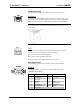
Front Panel Ports
The QM-RX front panel ports are illustrated and described as follows.
QM
8
1
QM (Input)
The 8-pin RJ-45 QuickMedia transport port accepts CAT5E or CAT6 video
and control signals. The QM input port conforms to the 568B wiring standard.
Refer to page 2 and page 12 for additional QuickMedia wiring information.
NOTE: To determine the location of pin 1 on an RJ-45 male connector, hold
the connector with the cable down and the clip facing away from you. Pin 1 is
on the far left.
NET
The four-pin 5 mm detachable terminal block NET connector is used for
connection to Cresnet and expansion to other peripherals.
Pins 24 and G provide 24 VDC and ground.
Pins Y and Z provide communications (data).
Power to the unit (8 W) is supplied through this connector.
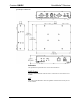
Rear Panel Ports
The QM-RX rear panel ports are illustrated and described as follows.
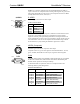
RGBHV
1
10
15
RGBHV
One DB15HD female connector is provided for RGB video output.
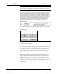
DB15HD Connector Pinout
PIN DESCRIPTION PIN DESCRIPTION
1 Red Signal 9 N/C
2 Green Signal 10 Sync Ground
3 Blue Signal 11 N.C.
4 Reserved 12 Pullup
5 Ground 13 Horizontal Sync
6 Red Ground 14 Vertical Sync
7 Green Ground 15 Pullup
8 Blue Ground
● QuickMedia Receiver: QM-RX Operations Guide – DOC. 6333
8