
Installation guide


Crestron QM-FTCC-TPS4 FlipTop Touchpanel Computer Center
latest version of the QM-RMCRX-BA QuickMedia Receiver/Processor Operations
Guide (Doc. 6332) or the Crestron e-Control Reference Guide (Doc. 6052). These
documents are available from the Crestron website. Refer to the following figure for
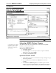
a typical connection diagram when uploading files.
Typical Connection Diagram when Uploading
QuickMedia Cable
Cresnet Cable
QM-FTCC-TPS4 (Underside)
QM-RMCRX-BA (Front)
QM-RMCRX-BA (Rear)
Computer
Null-modem RS-232 cable with DB9
female connectors on both ends
COM BCOM A
RELAY OUTPUT
1
2
G
RGBHV
VIDEOS-VIDEO
AUDIO
INPUT
I
R
SPCH
L
R
+ - G
+ - G + - G
1 2 3 4 G
S G
QM
QM LINK
LAN
NET
NET
PWR
ACT
SW-RHW-R
IR
INPUT
COM A
COM B
SPEAKER
LR
+ -
+ -
24V DC
2.0A
24 Y Z G
24 Y Z G
NOTE: Use a standard DB9 “Null-Modem” cable for connection to a
QM-Series processor. Use a straight-through serial cable for connection to a
2-Series processor.
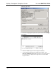
1. Open Crestron Toolbox and click Tools | Manage Address Book to display
the communications settings. The DefaultAddressBook.adr file contains
several default address settings. Select Serial on COM 1 for serial
communication.
Operations & Installation Guide – DOC. 6393 FlipTop Touchpanel Computer Center: QM-FTCC-TPS4 • 33