
Installation guide


Crestron QM-FTCC-TPS4 FlipTop Touchpanel Computer Center
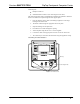
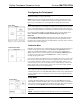
Underside Connections
ETHERNET:
10/100
BASE-T
ETHERNET
TO LAN
GROUND
QM OUTPUT:
QUICKMEDIA PORT CARRIES
AUDIO, VIDEO, RGB, AND
MICROPHONE SIGNALS TO
QUICKMEDIA RECEIVER
CRESNET:
TO CONTROL
SYSTEM AND
OTHER
CRESNET
DEVICES
TSID SETUP
BUTTON AND LED
IEC-320 ELECTRICAL
APPLIANCE
COUPLER
(INTERNATIONAL
MODELS ONLY)
MIC/LINE LEVEL INPUTS:
CONNECT TO TWO
BALANCED CONDENSER
OR DYNAMIC MICROPHONES
OR BALANCED/UNBALANCED
LINE LEVEL SOURCES
120 VAC LINE CORD
(DOMESTIC MODELS ONLY)
COMPUTER INPUT:
CONNECTS COMPUTER
RGB VIDEO OUTPUT TO
THE PRESENTATION
SYSTEM.
AUDIO INPUT:
CONNECTS TO
COMPUTER
SOUND CARD
OUTPUT
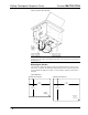
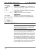
Ground Wire Connections
Proper grounding is required. Connect the ground from the QM transmitter
(QM-FTCC-TPS4) to earth ground. Connect the Cresnet shield at the
QM-RMCRX-BA to the chassis ground provided on the QM-RMCRX-BA. The
QM-RMCRX-BA chassis must also be connected to an earth ground (building steel).
Refer to the following grounding diagram.
Ground Wire Connections
QM-RMCRX-BA
QM-FTCC-TPS-4
24
Y
Z
G
Shield
Ground
Wire to
Earth
Ground
Ground
Terminal
to Earth
Ground
Cresnet
Ground Wire
NOTE: Do not connect the shield to earth ground at the QM-FTCC-TPS4.
Operations & Installation Guide – DOC. 6393 FlipTop Touchpanel Computer Center: QM-FTCC-TPS4 • 21