
System information


Crestron 2-Series Control Systems Reference Guide
Reference Guide – DOC. 6256A 2-Series Control Systems • 5
Establishing Communications with the Control System
Whether uploading programs, troubleshooting, or performing diagnostics
communication between the control system and a PC must be established.
In electronic terms, a “console” provides a means of communication between an
operator and the central processing unit of a computer. Crestron Toolbox lets you
talk to the console of a 2-Series dual bus control system. Crestron Toolbox allows
the operator to establish, monitor, and troubleshoot communications directly with the
control system.
Depending on the control system’s capabilities, the following communication
protocols may be used to communicate with a control system:
• Serial communication (RS-232) with a PC via the COMPUTER port
on the control system
• Ethernet communication via CTP (Crestron Terminal Protocol –
reserved port number, default port is 41795) *
• Ethernet communication via Secure CTP over a SSL connection to port
41797 at the IP address of the processor*
• Telnet (default port is 23)*
• Cresnet for processors operating in the Cresnet slave mode (refer to
“Master-Slave Modes” on page 32)
* These methods are only available if the control system supports Ethernet.
Whether the intent is to use RS-232 or Ethernet, these methods initially require
connection of the control system to a PC via RS-232.
Another method for submitting a command to the console is to use the “Console” or
“User Program Commands “ symbols in SIMPL Windows in the control system
program. The Console symbol transmits and receives serial data to and from the
control system’s console. The User Program Commands symbol allows data typed at
the console to be sent to the program. For more information on the Console symbol,
refer to “Console Logic Symbol” on page 16. For more information on the User
Program Commands symbol, refer to “User Program Commands Symbol” on page
17.
Serial Connection
Complete the following steps to establish a serial connection between a PC and a
control system.
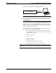
1. As shown in the following diagram, connect the COMPUTER port on the
control system to one of the COM ports (usually COM 1) on the PC. Use a
straight-through RS-232 cable with a DB9 male connector on one end and a
DB9 female connector on the other. Most commercially available cables are
acceptable; they should have at least five pins for transmit, receive, ground,
and hardware handshaking (pins 2, 3, 5, 7, 8).
NOTE: Most of the Crestron 2-Series control systems use a straight-
through RS-232 cable. However, some models use a null-modem cable.
Refer to your control system’s Operations Guide for cable details.