
System information


Crestron 2-Series Control Systems Reference Guide
Reference Guide – DOC. 6256A 2-Series Control Systems • 165
For example, join number 1 on the control room touchpanel, which activates Preset 1
in classroom 1, can be sent as join number 1 to classroom 1. Join number 16 on the
control room touchpanel, which activates Preset 1 in classroom 2 can be sent as join
number 1 to classroom 2. The same can be said for the return path; Join number 1
from classroom 1 can be mapped to feedback 1 on the control room touchpanel and
join number 1 from classroom 2 can be mapped to feedback 16 on the control room
touchpanel.
Ultimately, the program for each classroom can have the same set of join numbers
that go to and from the control room touchpanel; Only the control room touchpanel
must use different join numbers.
In the JNR program that resides on the control room touchpanel, join numbers 1
through 15 in classroom 1 (IP ID 3) can be mapped to join numbers 1 through 15 on
the control room touchpanel, join numbers 1 through 15 in classroom 2 (IP ID 4) can
be mapped to join numbers 16 through 30 on the control room touchpanel, and join
numbers 1 through 15 in classroom 3 (IP ID 5) can be mapped to join numbers 31
through 45 on the control room touchpanel.
Since the IP ID for each room program is the same, a “Device ID” can be used in the
control room touchpanel’s IP table to individually address each IP ID. A Device ID
is comprised of an IP ID and an IP address. A set of entries in the IP table can share
the same IP ID as long as a Device ID is used to differentiate between them. This
allows us to say that "Device ID 20" really means "IP ID 03 on 192.168.1.10" and
"Device ID 21" really means "IP ID 03 on 192.168.1.11". The Device ID is
arbitrarily chosen; the only thing to keep in mind is that the Device ID in the remap
project must also be configured in the IP table of the TPS panel. Following are
sample Device ID definitions for each classroom:
For Classroom 1:
Device ID 20 is made up of data to/from IP ID 03 from IP Address 192.168.1.10
For Classroom 2:
Device ID 21 is made up of data to/from IP ID 03 from IP Address 192.168.1.11
For Classroom 3:
Device ID 22 is made up of data to/from IP ID 03 from IP Address 192.168.1.12
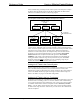
Following is a graphical representation of the network.
Isys Touchpanel Communicating to Multiple Control Systems via Ethernet
CONTROL ROOM Isys TOUCHPANEL
IP ADDR: 192.168.1.14
IP TABLE
DEV ID: 20
IP ID: 03
IP ADDR:
192.168.1.10
DEV ID: 21
IP ID: 03
IP ADDR:
192.168.1.11
DEV ID: 22
IP ID: 03
IP ADDR:
192.168.1.12
ETHERNET
COMMUNICATION
CLASSROOM 1
IP ADDR:
192.168.1.10
IP TABLE
IP ID: 03
IP ADDR:
192.168.1.14
CLASSROOM 2
IP ADDR:
192.168.1.11
IP TABLE
IP ID: 03
IP ADDR:
192.168.1.14
CLASSROOM 3
IP ADDR:
192.168.1.12
IP TABLE
IP ID: 03
IP ADDR:
192.168.1.14