
System information


Crestron 2-Series Control Systems Reference Guide
Reference Guide – DOC. 6256A 2-Series Control Systems • 159
(ftp://ftp.crestron.com/Examples/). Download and extract the ZIP files
“JNR_Example_2SERIES_Frame_example_old.zip”,
“JNR_Touch_Panel_Example.zip” and “jnr_large_tps_panel_example.zip” for a
program that was written using JNR to access Reserved Join Numbers.
To put the touchpanel in the Setup Mode using a JNR program, a button press must
be created in the touchpanel symbol of the control system program.
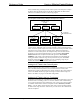
TPS-6000 in Slot 9 of a PRO2 Control System
In the JNR program, the press number used in the control system’s touchpanel
symbol must be matched to the corresponding press number on the TPS Cresnet
Interface symbol. The Cresnet Interface press is then connected to the Run_Setup
line (reserved join number 17242) on the System Reserved Joins symbol.
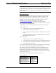
TPS Cresnet Interface Symbol
TPS Screen Interface (System Reserved Joins) Symbol
Cresnet
When using Cresnet for carrying signals to and from the touchpanel, the remap
program must have a TPS Cresnet Interface symbol. This symbol, as shown after this
paragraph, is identical to the TPS Screen Interface symbol. The important distinction
to be made is that the TPS Cresnet Interface symbol provides communication (inputs
and outputs) via the Cresnet port, whereas the TPS Screen Interface symbol relates
the physical press and feedback shown on the touchpanel screen. Therefore,
assuming Cresnet communication with feedback, a physical button press on the