
System information


Crestron 2-Series Control Systems Reference Guide
Reference Guide – DOC. 6256A 2-Series Control Systems • 157
matching input or in the absence of any input may be prompted during bootup of the
panel. Inputs to slots 5 through 12 may be received from a button press on the panel
or are commands sent over Cresnet, Ethernet, or the RS-232 port.
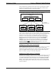
Communication Slots
Slots 20, 21, and 22 are referred to as communication slots because they depict the
three physical communication ports on an Isys panel with an Ethernet card installed.
In all cases, the input and output of the symbol representing these communication
slots can be thought of as signals arriving to and leaving the physical port. Therefore,
inputs and outputs from the Cresnet symbol are received from and delivered to all
connected Cresnet devices. Inputs and outputs on the RS-232 interface enter and
leave the panel via the RS-232 port to an RS-232 device connected to the system.
Likewise, the Ethernet interface is capable of transferring signals to and from
Ethernet devices assuming the Ethernet card has been installed into the touchpanel.
NOTE: The touchpanel’s RS-232 port must be in the Control mode to route signals
to and from the RS-232 port. Refer to the latest revision of the touchpanel operations
guide for instructions on selecting the control mode.
NOTE: Prior to adding any Ethernet devices to the system, a designer must add an
“Ethernet Device for TPS Panels” to the Ethernet slot. From the Device Library in
Configuration Manager, drag and drop the 'Ethernet Device for TPS Panels' from the
Ethernet Control Modules folder to slot 22.
The Remap Program
The purpose of remapping is to add Isys touchpanel features to a control system
program or to easily expand existing networked control systems. Programmers of a
brand new system have the advantage of starting from a “clean slate”. The
programmer can design the SIMPL Windows programs for the Crestron control
system and Isys panel simultaneously. This is important because they do not have to
worry about the remap program conflicting with the original program in the control
system. Even so, all programmers should be aware of a default behavior that
accompanies remapping. The default behavior of a JNR program states that an
unassigned touchpanel button press (no signal name in the remap program) will be
sent out over Cresnet, RS-232 (if available), and to each address in the touchpanel’s
IP table.
If a system already exists and new features are to be added using remapping, the
designer needs to be cautious. Use of remapping with join numbers already utilized
in an existing program can undermine the existing program. The programmer should
verify that no pre-existing functions are unintentionally lost while remapping
assigned join numbers. It is safer to implement remapping with previously unused
join numbers.
NOTE: In a program without remapping, a button press or a slider operation
(analog) sends the join to Cresnet and all entries in an IP table. Once a signal is
defined in a JNR Routing Table, the default functionality is removed and must be
accounted for in the control system program’s touchpanel symbol to achieve a
desired result (i.e. feedback).
In Programming Manager, the TPS Screen Interfaces (slots 1 through 12) and the
TPS RS-232 Interface (slot 20) are available from the Central Control Modules
folder in Program View. The TPS Cresnet Interface (slot 21) is part of the Network
Modules folder. If the Ethernet card has been installed into the panel and the Ethernet
Device for TPS Panels has been added, the TPS Ethernet Interface can be found in
the Ethernet folder. Notice that the Logic folder is commented out. Logic is not