
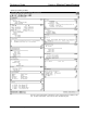
System information


Crestron 2-Series Control Systems Reference Guide
Reference Guide – DOC. 6256A 2-Series Control Systems • 11
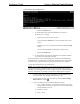
figure illustrates pinouts for straight through and crossover RJ-45 cables.
Pins 4, 5, 7, and 8 are not used.
RJ-45 Pinouts
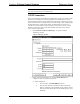
4. Open the address book in Crestron Toolbox by selecting Tools | Manage
Address Book or clicking
.
5. Create a new entry for the control system by clicking Add Entry or
pressing F3.
6. Enter a name for the control system connection and select TCP as the
connection type.
“Address Book” Window - Entering New TCP-IP Entry
7. Enter the IP address or hostname of the control system that was created on
page 10.
8. Click OK to save the address book entry.
9. To verify the connection, click the
icon. If the settings are correct, the
“System Info” window will be displayed.
Modem Connection
In applications where remote access to a control system is required but a serial or
Ethernet connection cannot be used, a modem can be connected to the control system
for communication with a PC console over a standard telephone line.