
Specifications


Crestron QM-RMC Room Media Controller
Rear Panel Ports
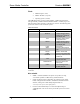
The QM-RMC rear panel ports are illustrated and described as follows.
INPUT
1 2 3 4 G
INPUT
This connector provides four software programmable digital inputs. Inputs are
Schmidt trigger type (nominal 2.5 V threshold) with 24 V input tolerance. For
detailed information, refer to “Slot 2: C21-DI04” on page 21.
Digital inputs are rated 0 – 24 VDC, 20K ohms input impedance.
IR
S G
IR
A 2-position mini-connector is a mini-implementation of a single PRO2 IR
port. The output is labeled S (signal) and G (ground). Infrared output is rated
up to 1.2 MHz, at data rates up to 9600 baud. Serial protocols include one-
way RS-232. For detailed information, refer to “Slot 1: C2I-IR1” on page 20.
COM B
COM A
COM (A & B)
These two DB9 (male) software programmable, bi-directional serial ports are
available for RS-232 communication, with hardware and software
handshaking and modem control. Speeds are rated up to 115,200 bps.
COM B is used as the console port.
Standard COM DB9 Pinout
PIN DIRECTION DESCRIPTION
1 TO QM-RMC (DCD) Data Carrier Detect
2 To QM-RMC (RXD) Receive Data
3 From QM-RMC (TXD) Transmit Data
4 From QM-RMC (DTR) Data Terminal Ready
5 Common (SG) Signal Ground
7 From QM-RMC (RTS) Request To Send
8 To QM-RMC (CTS) Clear To Send
9 To QM-RMC (RI) Ring Indicator
Memory
The QM-RMC has 36MB of built-in memory (non-volatile and volatile). The
total of 36MB is specified as follows: 4MB flash (non-volatile), 32MB SDRAM
(volatile), and 256KB NVRAM (battery backed up). Flash memory contains the
file system inside the 2-Series control engine. Non-volatile memory contains
information that is retained after the loss of electrical power. Volatile memory is
lost after a power failure. Refer to the following lists for a breakdown of
memory usage for program-related information stored in the unit.
Operations Guide – DOC. 6161 Room Media Processor: QM-RMC • 7