
Specifications


infiNET™ DIMMERS
Installation
WARNING: Turn off power at the circuit breaker.
Installing with power on can result in serious personal
injury and damage to the device.
NOTE: The -DIM1RF, -DIM4RF, -DIMS1RF,
-DIMS4RF, and -SLVD1RF require a neutral wire in the
wallbox for operation. If no neutral is present, contact a
licensed electrician for installation or refer to the
alternative wiring diagrams described in “Appendix:
Wiring Diagrams” on page 9.
NOTE: The -DIMS1RF and -DIMS4RF must be
installed in the same wallbox that contains the
connections to the load.
NOTE: New installations should be checked for short
circuits prior to installing an infiNET dimmer. With
power off, close the circuit and restore power. If the lights
do not work or a breaker trips, check and correct the
wiring or fixture (if necessary). Install the dimmer only
when the short is no longer present. The warranty is
void if the dimmer is installed and operated with a
shorted load.
When installing a -DIMXRF or a -DIMSXRF without a
slave, follow the instructions in “Wiring a -DIM(S)XRF
(No Slaves)” below. If wiring a -DIMSXRF with a
-SLVD1RF, refer to “Wiring a -DIMSXRF with One or
More -SLVD1RFs” in the next column.
Wiring a -DIM(S)XRF (No Slaves)
The following describes the installation of a stand-alone
-DIM1RF, -DIM4RF, -DIMS1RF or -DIMS4RF.
1. Turn power off at the circuit breaker.
2. Wire the dimmer as shown in Figure 1 on
page 9.
NOTE: The RED (Load) and BLACK (Hot)
wires are #14 AWG. The BLUE (Slave) and
WHITE (Neutral) wires are #18 AWG. The
GREEN (Ground) wire is #16 AWG.
NOTE: Since the -DIMS1RF or -DIMS4RF is
installed without a -SLVD1RF, the BLUE lead
(Slave) should be capped.
Alternative Wiring
For situations where a neutral is not present or
other scenarios that may be encountered during
installation, refer to the “Stand-Alone
Installations” section of “Appendix: Wiring
Diagrams” on page 9.
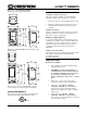
3. Push all power wires back into the wallbox and
fasten the device to the wallbox with the
provided screws.
4. Attach decorative faceplate.
5. Restore power at the circuit breaker.
Wiring a -DIMSXRF with One or More
-SLVD1RFs
NOTE: The -DIMS1RF and -DIMS4RF must be installed
in the same wallbox that contains the connections to the
load.
The following describes installation of a -DIMSXRF
master with a -SLVD1RF slave.
1. Turn power off at the circuit breaker.
2. Wire the dimmers as shown in Figure 4 on
page 10.
NOTE: Do not connect the BLUE (Slave) wire
to the Black (Hot) or RED (Load) wires.
NOTE: The RED (Load) and BLACK (Hot)
wires are #14 AWG. The BLUE (Slave) and
WHITE (Neutral) wires are #18 AWG. The
GREEN (Ground) wire is #16 AWG.
NOTE: If a -DIMS1RF or -DIMS4RF is
installed without a -SLVD1RF, the BLUE lead
(Slave) should be capped.
NOTE: The WHITE (Neutral) connection on
the -SLVD1RF is optional and is only required
for operation of the LED. If the neutral is not
available, the white lead should be capped off.
Alternative Wiring
For situations where a neutral is not present or
other scenarios that may be encountered during
installation, refer to the “Master-Slave
Installations” section of “Appendix: Wiring
Diagrams” on page 10.
3. Push all power wires back into the wallbox and
fasten the devices to their respective wallboxes
with the provided screws.
4. Attach decorative faceplates.
5. Restore power at the circuit breaker.
Installation Guide – DOC. 6292C infiNET™ Wall Box Dimmer: CLW-DIM1/4RF, DIMS1/4RF, & SLVD1RF • 5