
Installation guide


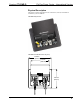

FlipTop Power Center – International Version Crestron FTI-PWR-D
Setup
Installation
NOTE: To prevent overheating, do not operate this product in an area that exceeds
the environmental temperature range listed in the specifications table. Consideration
must be given if installed inside a closed desk or in a closed podium since the
operating ambient temperature of these environments may be greater than the room
ambient temperature. Contact with thermal insulating materials should be avoided on
all sides of the unit.
Use the following steps to install the FTI-PWR-D.
Tools required:
• Phillips screwdriver (not included)
• Appropriate carpentry tools for cutout
Cable Management Kit
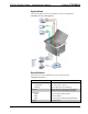
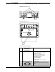
The FTI-PWR-D is shipped with a separate cable management kit for organizing
cables fed into the power center.
Parts Supplied for Cable Management Kit
DESCRIPTION PART NUMBER QUANTITY
Cable Support Plate 2023519 1
Bushings, 14 mm (0.55 in) ID,
20 mm (0.80 in) OD
2010496 2
Bushings, 10 mm (0.39 in) ID,
17 mm (0.64 in) OD
2011070 2
Bushings, 8 mm (0.31 in) ID,
13 mm (0.50 in) OD
2009522 4
Screws, #04-40 x 1/4" (~7 mm) 2007158 4
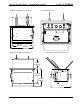
The cable support plate should be installed before mounting the FTI-PWR-D to a
surface. The cables are threaded through the cable support plate.
1. Place bushings on the cables you wish to install in the power center (eight
bushings supplied). Use bushings appropriate for the diameter of each
cable.
2. Thread the cables through the cable support plate slots appropriate for the
size of the cable and the bushing you attached in the previous step.
3. Snap the bushings into the slots on the cable support plate.
4. Feed all excess cable through the opening.
5. Attach the cable support plate using the four #04-40 x 1/4" (~7 mm) screws.
6. If desired, any installed cables can be secured to the bottom bar with tie
wraps (not supplied).
6 • FlipTop Power Center – International Version: FTI-PWR-D Operations & Installation Guide – DOC. 6797B