
Specifications
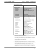

Isys 5.7” Wireless Touch Screens Crestron TPS-6X Series
12 • Isys 5.7” Wireless Touch Screens: TPS-6X Series Operations Guide – DOC. 6875C
• Each device using IP to communicate with a control system must have a
unique IP ID.
RF ID
Every TPS-6X communicating via RF with a Crestron control system through a
CEN(I)-ERFGW-POE gateway or directly with an MC2W control system, requires a
unique RF ID. The RF ID is a two-digit hexadecimal number that can range from 03
to 12. The RF ID of the unit, set using the internal setup menu (refer to
“WIRELESS” which starts on page 26
) or in Crestron Toolbox, must match the RF
ID specified in the SIMPL Windows program.
IR ID
Every TPS-6X communicating via IR with a Crestron control system through a
CNXRMIRD receiver, a C2N-IRGW gateway or directly with an MC2W control
system, requires a unique IR ID to secure IR communications. There are two useable
codes (two-digit hexadecimal numbers): 00 and 10; the default is 00. The IR ID of
the unit, set using the internal setup menu (refer to “WIRELESS
” which starts on
page 26), must match the IR ID specified in the SIMPL Windows program.
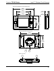
Battery Switch
The TPS-6X ships with the battery switch (on the rear) in the OFF (downward)
position. The OFF position is used for shipping and long term storage only.
Use the included T-pin to turn the switch ON (slide it upward) and place the TPS-6X
on the included docking station/charger for a minimum of four hours before using.
NOTE: When the TPS-6X is on the docking station/charger, the front panel battery
LED flashes to indicate the battery is charging. When fully charged, it remains on,
without flashing.
To charge the internal battery, the TPS-6X must be placed on the TPS-6X-DS (or
with the TPS-6X-LP models, the TPS-6X-DS-LP or with the TPS-6XNL models, the
TPS-6XNL-DS) Docking Station, which must be connected to a powered
TPS-6X-IMCW Interface Module (both included).
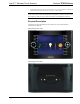
Configuring the Touch Screen
NOTE: The only connection required to configure the touch screen is power. Refer
to “Hardware Hookup” which starts on page 35 for details.
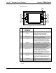
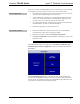
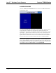
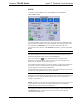
To configure the TPS-6X it may be necessary to access a series of setup menus prior
to viewing run-time screens that are loaded into the touch screen for normal
operation. The MAIN MENU is the starting point for configuring the touch screen.
NOTE: If no project has been loaded or if an invalid project has been loaded, the
touch screen displays an error message and asks the user to touch the screen to enter
setup, which defaults to the MAIN MENU.
NOTE: Trigger key functionality is not available in the setup menus.