
Installation guide

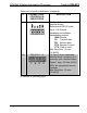

Crestron DIN-AP2 DIN Rail 2-Series Automation Processor
Connectors, Controls & Indicators (Continued)
# CONNECTORS
1
,
CONTROLS &
INDICATORS
DESCRIPTION
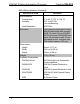
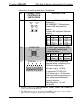
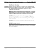
11 LAN
3
GREEN
LED
YELLOW
LED
PIN 8
PIN 1
(1) 8-wire RJ-45 with 2 LED
indicators;
10/100BASE-T Ethernet port;
Green LED indicates link
status;
Yellow LED indicates Ethernet
activity
PIN SIGNAL PIN SIGNAL
1 TX + 5 N/C
2 TX - 6 RC -
3 RC + 7 N/C
4 N/C 8 N/C
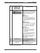
12 COMPUTER
Pin 1 Pin 2
Pin 4 Pin 3
(1) USB Type B female, USB
1.1 computer console port
(cable included)
PIN SIGNAL PIN SIGNAL
1 +5 VDC 3 Data +
2 Data - 4 Ground
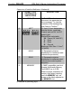
13 IR/SERIAL 1 – 4
(1) 8-pin 3.5mm detachable
terminal block comprising four
IR/Serial output ports;
IR output up to 1.2 MHz;
1-way serial TTL/RS-232
(0-5 Volts) up to 115.2k baud;
Individual signal generator per
port, allowing simultaneous
firing of all ports;
Max Wire Size: 1.5 mm
2
(16 AWG)
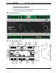
1. Interface connectors for NET, IR/SERIAL, COM 1, COM 2, I/O and RELAYS
ports are provided with the unit.
2. The DIN-AP2 can only be powered via the NET port. Be sure to use a Crestron
approved power supply as another may cause damage.
Operations & Installation Guide – DOC. 6662C DIN Rail Automation Processor: DIN-AP2 • 11