
Installation guide

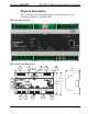

DIN Rail 2-Series Automation Processor Crestron DIN-AP2
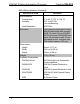
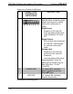
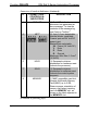
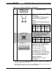
Connectors, Controls & Indicators
# CONNECTORS
1
,
CONTROLS &
INDICATORS
DESCRIPTION
1 I/O 1 – 8
(1) 9-pin 3.5 mm detachable
terminal block comprising eight
digital input/output or analog
input ports (referenced to
GND);
Digital Input:
Rated for 0-24 Volts DC;
Input impedance 20k ohms;
Logic threshold 1.25 Volts
DC
Digital Output:
250 mA sink from maximum;
24 Volts DC, catch diodes
for use with “real world”
loads
Analog Input:
Rated for 0-10 Volts DC,
protected to 24 Volts DC
maximum;
Input impedance 20k ohms;
Programmable 5 Volts, 2k
ohms pull-up resistor per pin;
Max Wire Size: 1.5 mm
2
(16 AWG)
2 POWER LED (1) Green LED, indicates
power supplied to unit via
either NET port
3 NET LED (1) Yellow LED, indicates
Cresnet bus activity
(Continued on following page)
8 • DIN Rail Automation Processor: DIN-AP2 Operations & Installation Guide – DOC. 6662C