Crestron DIN-AP2 DIN Rail 2-Series Automation Processor Operations & Installation Guide
This document was prepared and written by the Technical Documentation department at: Crestron Electronics, Inc. 15 Volvo Drive Rockleigh, NJ 07647 1-888-CRESTRON Crestron, the Crestron logo, Cresnet, Crestron Toolbox, D3 Pro, e-Control, RoomView and SIMPL+ are trademarks or registered trademarks of Crestron Electronics, Inc. in the United States and other countries.
Regulatory Compliance This product is Listed to applicable UL Standards and requirements by Underwriters Laboratories Inc. As of the date of manufacture, the DIN-AP2 has been tested and found to comply with specifications for CE marking and standards per EMC and Radiocommunications Compliance Labelling. Federal Communications Commission (FCC) Compliance Statement This device complies with part 15 of the FCC Rules.
Crestron DIN-AP2 DIN Rail 2-Series Automation Processor Contents Crestron DIN Rail 2-Series Automation Processor: DIN-AP2 1 Introduction ............................................................................................................................... 1 Features and Functions ................................................................................................ 1 Applications...........................................................................................................
Crestron DIN-AP2 DIN Rail 2-Series Automation Processor DIN Rail 2-Series Automation Processor: DIN-AP2 Introduction The DIN-AP2 is a 2-Series control processor designed for small to medium-sized lighting and automation applications. DIN rail mounting enables modular installation alongside Crestron® DIN rail lighting and automation control modules and other third-party DIN rail mountable devices.
DIN Rail 2-Series Automation Processor Crestron DIN-AP2 2-Series Processor Built upon Crestron's reliable 2-Series control engine, the DIN-AP2 is extensively programmable using Crestron's suite of powerful development software and vast database of drivers and software modules. The DIN-AP2 works seamlessly with Crestron's entire line of lighting dimmers and shade controls, keypads and touch screens, thermostats, wireless gateways, and expansion modules.
Crestron DIN-AP2 DIN Rail 2-Series Automation Processor separately) is required to power the DIN-AP2 and any connected Cresnet devices. Ethernet and e-Control®2 Built-in 10/100 Ethernet facilitates secure high-speed network connectivity, enabling extensive capabilities for remote system maintenance and control, and providing an interface to other Crestron control systems.
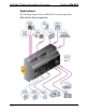
DIN Rail 2-Series Automation Processor Crestron DIN-AP2 Applications The following diagram shows a DIN-AP2 in a typical application. DIN-AP2 in a Typical Application 4 • DIN Rail Automation Processor: DIN-AP2 Operations & Installation Guide – DOC.
Crestron DIN-AP2 DIN Rail 2-Series Automation Processor Specifications Specifications for the DIN-AP2 are listed in the following table.
DIN Rail 2-Series Automation Processor Crestron DIN-AP2 DIN-AP2 Specifications (Continued) SPECIFICATION DETAILS Environmental Temperature Humidity Heat Dissipation Enclosure 0° to 40 °C (32° to 104 °F) 10% to 90% RH (non-condensing) 26 BTU/Hr Light gray polycarbonate housing with polycarbonate label overlay, UL94 V-0 rated, 35 mm DIN EN 60715 rail mount, DIN 43880 form factor for enclosures with 45 mm front panel cutout, occupies nine DIN module spaces (162 mm) Dimensions Height Width Depth Weight A
Crestron DIN-AP2 DIN Rail 2-Series Automation Processor Physical Description This section provides information on the connections, controls and indicators available on your DIN-AP2. DIN-AP2 Physical View DIN-AP2 Overall Dimensions 1 6 159 mm (6.26 in) 8 10 12 58 mm (2.28 in) 94 mm (3.71 in) 90 mm (3.54 in) 2 3 4 5 7 9 11 13 Operations & Installation Guide – DOC.
DIN Rail 2-Series Automation Processor Crestron DIN-AP2 Connectors, Controls & Indicators # CONNECTORS1, CONTROLS & INDICATORS DESCRIPTION 1 I/O 1 – 8 2 POWER LED 3 NET LED (1) 9-pin 3.5 mm detachable terminal block comprising eight digital input/output or analog input ports (referenced to GND); Digital Input: Rated for 0-24 Volts DC; Input impedance 20k ohms; Logic threshold 1.
Crestron DIN-AP2 DIN Rail 2-Series Automation Processor Connectors, Controls & Indicators (Continued) # CONNECTORS1, CONTROLS & INDICATORS DESCRIPTION 4 MSG LED 5 NET2 6 HW-R 7 SW-R 8 MEMORY (1) Red LED, indicates processor has generated an error message. To view the contents of the message log, use Crestron Toolbox™. (2) 4-pin 3.
DIN Rail 2-Series Automation Processor Crestron DIN-AP2 Connectors, Controls & Indicators (Continued) # CONNECTORS1, CONTROLS & INDICATORS DESCRIPTION 9 COM 1 – 2 10 RELAYS 1 – 4 (2) 5-pin 3.5 mm detachable terminal blocks; Bidirectional RS-232 ports; Up to 115.2k baud; Hardware and software handshaking support GND: Ground TX: Transmit data RX: Receive data RTS: Request to send CTS: Clear to send Max Wire Size: 1.5 mm2 (16 AWG) (1) 8-pin 3.
Crestron DIN-AP2 DIN Rail 2-Series Automation Processor Connectors, Controls & Indicators (Continued) # CONNECTORS1, CONTROLS & INDICATORS DESCRIPTION 11 LAN3 (1) 8-wire RJ-45 with 2 LED indicators; 10/100BASE-T Ethernet port; Green LED indicates link status; Yellow LED indicates Ethernet activity GREEN LED PIN 8 YELLOW LED PIN 1 PIN 1 2 3 4 12 COMPUTER Pin 4 Pin 1 13 Pin 3 Pin 2 IR/SERIAL 1 – 4 SIGNAL TX + TX RC + N/C PIN 5 6 7 8 SIGNAL N/C RC N/C N/C (1) USB Type B female, USB 1.
DIN Rail 2-Series Automation Processor Crestron DIN-AP2 Setup Network Wiring When wiring the Cresnet® and Ethernet network, consider the following: NOTE: DMNet wiring and Cresnet wiring are not compatible. Use Crestron Certified Wire. NOTE:Cresnet-HP wire cannot be used. Use Crestron power supplies for Crestron equipment. Provide sufficient power to the system. CAUTION: Insufficient power can lead to unpredictable results or damage to the equipment.
Crestron DIN-AP2 DIN Rail 2-Series Automation Processor The DIN-AP2 is designed for installation on a DIN rail. Refer to the following diagram when installing. Installing the DIN-AP2 1. Place the top of the DIN-AP2’s rail mount over the top of the DIN rail. 2. Tilt the bottom of the DIN-AP2 toward the DIN rail until it snaps into place. NOTE: When mounting DIN rail products, it may be necessary to use a flat-head screw driver to pull the DIN rail release tab while snapping the device onto the DIN rail.
DIN Rail 2-Series Automation Processor Crestron DIN-AP2 Hardware Hookup Connect the Device Make the necessary connections as called out in the illustration on the following page. Refer to “Network Wiring” on page 12 before attaching the 4-position terminal block connector. Apply power after all connections have been made. WARNING: Prior to connecting the device, turn off power at the circuit breaker. Failure to do so may result in serious personal injury or damage to the device.
Crestron DIN-AP2 DIN Rail 2-Series Automation Processor Hardware Connections for the DIN-AP2 I/O: To Controllable Devices & From Device Outputs MEMORY: For Optional MMC Compatible Memory Card NET: Power from DIN-PWS50 or Other Cresnet Power Supply.
DIN Rail 2-Series Automation Processor Crestron DIN-AP2 NOTE: The DIN-AP2 can only be powered by the 4-position terminal block connector labeled NET. Versiport Connections Depending on the application, the DIN-AP2’s Versiports can be wired multiple ways. Refer to the following diagrams when wiring a Versiport. WARNING: Incorrect wiring may damage the DIN-AP2 or the connected device. NOTE: The settings for input/output and the pull-up resistor are specified in the control system program.
Crestron DIN-AP2 DIN Rail 2-Series Automation Processor Versiport Wiring Diagrams - Analog Input Function Versiport Wiring Diagrams - Digital Output Function Operations & Installation Guide – DOC.
DIN Rail 2-Series Automation Processor Crestron DIN-AP2 Programming Software Have a question or comment about Crestron software? Answers to frequently asked questions (FAQs) can be viewed in the Online Help section of the Crestron Web site. To post a question or view questions you have submitted to Crestron’s True Blue Support, log in at http://support.crestron.com. First-time users will need to establish a user account.
Crestron DIN-AP2 DIN Rail 2-Series Automation Processor As with all Crestron software, D3 Pro provides extensive right-click and drag-and-drop functionality in addition to convenient keyboard shortcuts for frequently used functions and commands. Programming is organized into six system Views of the lighting system, each providing a moveable toolbox of devices such as interfaces, fixtures and control modules.
DIN Rail 2-Series Automation Processor Crestron DIN-AP2 Uploading and Upgrading Crestron recommends using the latest programming software and that each device contains the latest firmware to take advantage of the most recently released features. However, before attempting to upload or upgrade it is necessary to establish communication. Once communication has been established, files (for example, programs or firmware) can be transferred to the control system (and/or device).
Crestron DIN-AP2 DIN Rail 2-Series Automation Processor marked Ethernet however, communications must be established in order to see this information in the “System Info” window. icon); 2. Display the DIN-AP2’s “System Info” window (click the communications are confirmed when the device information is displayed. TCP/IP Ethernet Communication PC Running Crestron Toolbox LAN DIN-AP2 The DIN-AP2 connects to PC via Ethernet: 1. Establish USB communication between DIN-AP2 and PC. 2.
DIN Rail 2-Series Automation Processor Crestron DIN-AP2 8. When using the DIN-AP2 as a “slave”, edit the “master” control system’s IP table to include an entry for the DIN-AP2. The entry should list the DIN-AP2’s IP ID (specified on the DIN-AP2’s IP table) and its IP address. Programs and Firmware Program or firmware files may be distributed from programmers to installers or from Crestron to dealers.
Crestron DIN-AP2 DIN Rail 2-Series Automation Processor Problem Solving Troubleshooting The following table provides corrective action for possible trouble situations. If further assistance is required, please contact a Crestron customer service representative. DIN-AP2 Troubleshooting TROUBLE POSSIBLE CAUSE(S) CORRECTIVE ACTION Unexpected response from control system. Network devices are not communicating with the control system. Use Crestron Toolbox to poll the network.
DIN Rail 2-Series Automation Processor Crestron DIN-AP2 DIN-AP2 Troubleshooting (Continued) TROUBLE MSG LED illuminates. POSSIBLE CAUSE(S) CORRECTIVE ACTION Hardware or software failure, hardware incompatibility with software definitions or programming error. Verify that hardware configuration matches software configuration. Use Crestron Toolbox to display the error log. Refer to “Error Message Definitions” in the latest version of the Crestron 2-Series Control Systems Reference Guide (Doc.
Crestron DIN-AP2 DIN Rail 2-Series Automation Processor DIN-AP2 Troubleshooting (Continued) TROUBLE Cresnet device does not respond. POSSIBLE CAUSE(S) Device not wired correctly. Improper Net ID used. Device is not receiving sufficient power. CORRECTIVE ACTION Verify Cresnet wiring. Verify that device ID matches Net ID in the program. Use the Crestron Power Calculator to help calculate how much power is needed for the system.
DIN Rail 2-Series Automation Processor Crestron DIN-AP2 6. Once the DIN-AP2 is in Monitor mode, connect to the PC using a USB cable. NOTE: If at any point in the above sequence, one of the timer periods expires without the SW-R button being pressed, the unit will boot normally, first running the firmware, then loading the application.
Crestron DIN-AP2 DIN Rail 2-Series Automation Processor 12. Find and select the correct firmware file (.CUZ or .zip) and click Open. 13. In the “Firmware” window, click Send. You will see a “Confirmation” window asking if you’ve selected the right file. Click OK and you will see the “File Transfer” window. 14. When file transfer is completed, you will see a window asking you to re-connect. Click OK, then close the “Firmware” window and re-connect using the normal Address Book entry.
DIN Rail 2-Series Automation Processor Crestron DIN-AP2 When calculating the length of wire for a particular Cresnet run, the wire gauge and the Cresnet power usage of each network unit to be connected must be taken into consideration. Use Crestron Certified Wire only. If Cresnet units are to be daisy-chained on the run, the Cresnet power usage of each network unit to be daisy-chained must be added together to determine the Cresnet power usage of the entire chain.
Crestron DIN-AP2 DIN Rail 2-Series Automation Processor Reference Documents The latest version of all documents mentioned within the guide can be obtained from the Crestron Web site (www.crestron.com/manuals).
DIN Rail 2-Series Automation Processor Crestron DIN-AP2 Software License Agreement This License Agreement (“Agreement”) is a legal contract between you (either an individual or a single business entity) and Crestron Electronics, Inc. (“Crestron”) for software referenced in this guide, which includes computer software and as applicable, associated media, printed materials and “online” or electronic documentation (the “Software”).
Crestron DIN-AP2 DIN Rail 2-Series Automation Processor If You are a business or organization, You agree that upon request from Crestron or its authorized agent, You will within thirty (30) days fully document and certify that use of any and all Software at the time of the request is in conformity with Your valid licenses from Crestron of its authorized agent.
DIN Rail 2-Series Automation Processor Crestron DIN-AP2 Return and Warranty Policies Merchandise Returns / Repair Service 1. No merchandise may be returned for credit, exchange or service without prior authorization from CRESTRON. To obtain warranty service for CRESTRON products, contact an authorized CRESTRON dealer. Only authorized CRESTRON dealers may contact the factory and request an RMA (Return Merchandise Authorization) number.
Crestron DIN-AP2 DIN Rail 2-Series Automation Processor This page is intentionally left blank. Operations & Installation Guide – DOC.
Crestron Electronics, Inc. 15 Volvo Drive Rockleigh, NJ 07647 Tel: 888.CRESTRON Fax: 201.767.7576 www.crestron.com Operations & Installation Guide – DOC. 6662C (2020744) 10.11 Specifications subject to change without notice.