
Installation guide


Crestron C2COM-2/3 2-Series RS-232/422/485 Expansion Cards
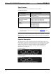
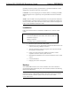
Sample Hookup Connections for C2COM-2 (top) and C2COM-3 (bottom)
Serial Device
Serial Device
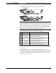
NOTE: The pinout of each 9-pin port is non-standard. Therefore, do not use a
straight-through DB9 cable. The following table contains pinout descriptions for
RS-232 and RS-422. Conflicts with some equipment may occur unless the controlled
devices are properly wired. Certain devices have specific voltage requirements.
Therefore, do not use all nine pins in a given application. Although the possibility is
remote, improper wiring may result in damage to the controlled device. Only the
required pins for each communication type should be connected.
Non-Standard COM Pinout (for RS-232 and RS-422 Communication)
PIN DIRECTION DESCRIPTION
1* To C2COM-2/3 (RXD-) RS-422 Receive Data (Idles low)
2 To C2COM-2/3 (RXD) RS-232 Receive Data
3 From C2COM-2/3 (TXD) RS-232 Transmit Data
4 From C2COM-2/3 (TXD+) RS-422 Transmit Data (Idles high)
5 Ground RS-232 and RS-422 Signal Common
6 To C2COM-2/3 (RXD+) RS-422 Receive Data (Idles high)
7 From C2COM-2/3 (RTS) RS-232 Request to Send
8 To C2COM-2/3 (CTS) RS-232 Clear to Send
9 From C2COM-2/3 (TXD-) RS-422 Transmit Data (Idles low)
*RS-422 transmit and receive are balanced signals requiring two lines plus a ground in each direction. RXD+
and TXD+ should idle high (going low at start of data transmission). RXD- and TXD- should idle low (going
high at start of data transmission). If necessary, RXD+/RXD- and TXD+/TXD- may be swapped to maintain
correct signal levels.
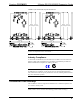
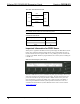
A common application is to use a three-wire null modem serial cable to
communicate with a PC, as shown in the following diagram. Since the pinouts on the
C2COM-2/3 are non-standard, the card should not be plugged into the PC directly.
The pinout in this illustration emulates the IBM PC AT connector except for the RS-
422 signals on pins 1, 4, 6, and 9.
Operations & Installation Guide - Doc. 8192 2-Series RS-232/422/485 Expansion Cards: C2COM-2/3 • 5