
Installation guide


2-Series RS-232/422/485 Expansion Cards Crestron C2COM-2/3
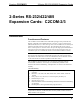
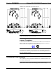
Three-Wire Null Modem Serial Cable
RED
WHITE
BLACK
RXD 2
TXD 3
GND 5
3 RXD
2 TXD
5 GND
9-PIN FEMALE
"D" CONNECTOR
9-PIN FEMALE
"D" CONNECTO
R
NOTE: To support RS-485, tie pin 1 (RXD-) to pin 9 (TXD-) and pin 4 (TXD+) to
pin 6 (RXD+) in the cable (refer to the following table).
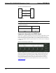
COM Pinout to RS-485 Bus
COM (DB9) CONNECTOR RS-485 BUS
Tie Pins 1 & 9 -
Tie Pins 4 & 6 +
Pin 5 G
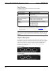
Important Information for PRO2 Users
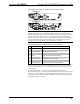
When power is applied to the PRO2, the front panel displays the Main Menu (shown
below). The COM menu function button (directly below COM) allows the user to
monitor transmission and reception traffic on every COM-type device and card that
is active in the SIMPL Windows program loaded in the control system, including the
C2COM-2/3.
PRO2 Front Panel (Sample of Main Menu)
When the COM button is pressed, (default front panel page) the display shows a list
of devices and cards to be monitored (one at a time). The user selects the slot and
port for the C2COM-2/3 by using the NEXT or PREV buttons on the panel. For
more information on viewing port traffic, refer to latest revision of the PRO2: 2-
Series Integrated Dual Bus Control System Operations Guide (Doc. 5957). It is
available from the Downloads | Product Manuals section of the Crestron website
(www.crestron.com
).
6 • 2-Series RS-232/422/485 Expansion Cards: C2COM-2/3 Operations & Installation Guide - Doc. 8192