
Installation guide

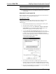
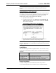
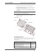
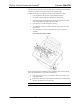

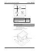
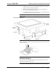
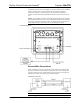
Table Of Contents
FlipTop Control Center with Cresnet
®
Crestron C2N-FTB
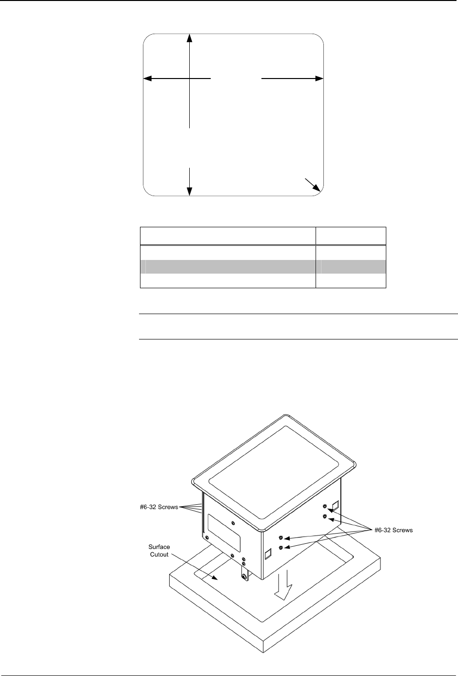
Cutout Dimensions
5.3125 in
(5 5/16 in)
(13.494 cm)
6.375 in
(6 3/8 in)
(16.19 cm)
Maximum
Radius
0.125 in
(0.318 cm)
Mounting Parts Supplied with the C2N-FTB
PART DESCRIPTION QUANTITY
#6-32, 3/16” Pan Head, Phillips Screw 8
#10-32, 2” Pan Head, Phillips Screw 4
Mounting Bracket 2
A Phillips screwdriver is required to mount the C2N-FTB to a surface.
NOTE: Before inserting the C2N-FTB in the mounting hole, ensure that all
required cables have been installed.
1. Install the eight supplied #6-32 screws, but do not tighten (four on the
front side and four on the rear side). These will be used to secure the
front and rear mounting brackets.
2. Position the C2N-FTB in the mounting hole.
Mounting Bracket Screw Locations
14 • FlipTop Control Center with Cresnet
®
: C2N-FTB Operations & Installation Guide - DOC. 6338