
Installation guide

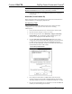
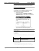
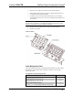
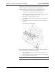

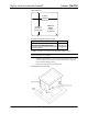
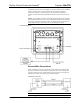
Table Of Contents
Crestron C2N-FTB FlipTop Control Center with Cresnet
®
CAUTION: Use only Crestron power supplies for Crestron equipment. Failure
to do so could cause equipment damage or void the Crestron warranty.
NOTE: When installing network wiring, refer to the latest revision of the
wiring diagram(s) appropriate for your specific system configuration, available
from the Crestron website.
When calculating the wire gauge for a particular Cresnet run, the length of the
run and the Cresnet power usage of each network unit to be connected must be
taken into consideration. If Cresnet units are to be daisy-chained on the run, the
Cresnet power usage of each unit to be daisy-chained must be added together to
determine the Cresnet power usage of the entire chain. If the unit is a home-run
from a Crestron system power supply network port, the Cresnet power usage of
that unit is the Cresnet power usage of the entire run. The length of the run in
feet and the Cresnet power usage of the run should be used in the resistance
equation below to calculate the value on the right side of the equation.
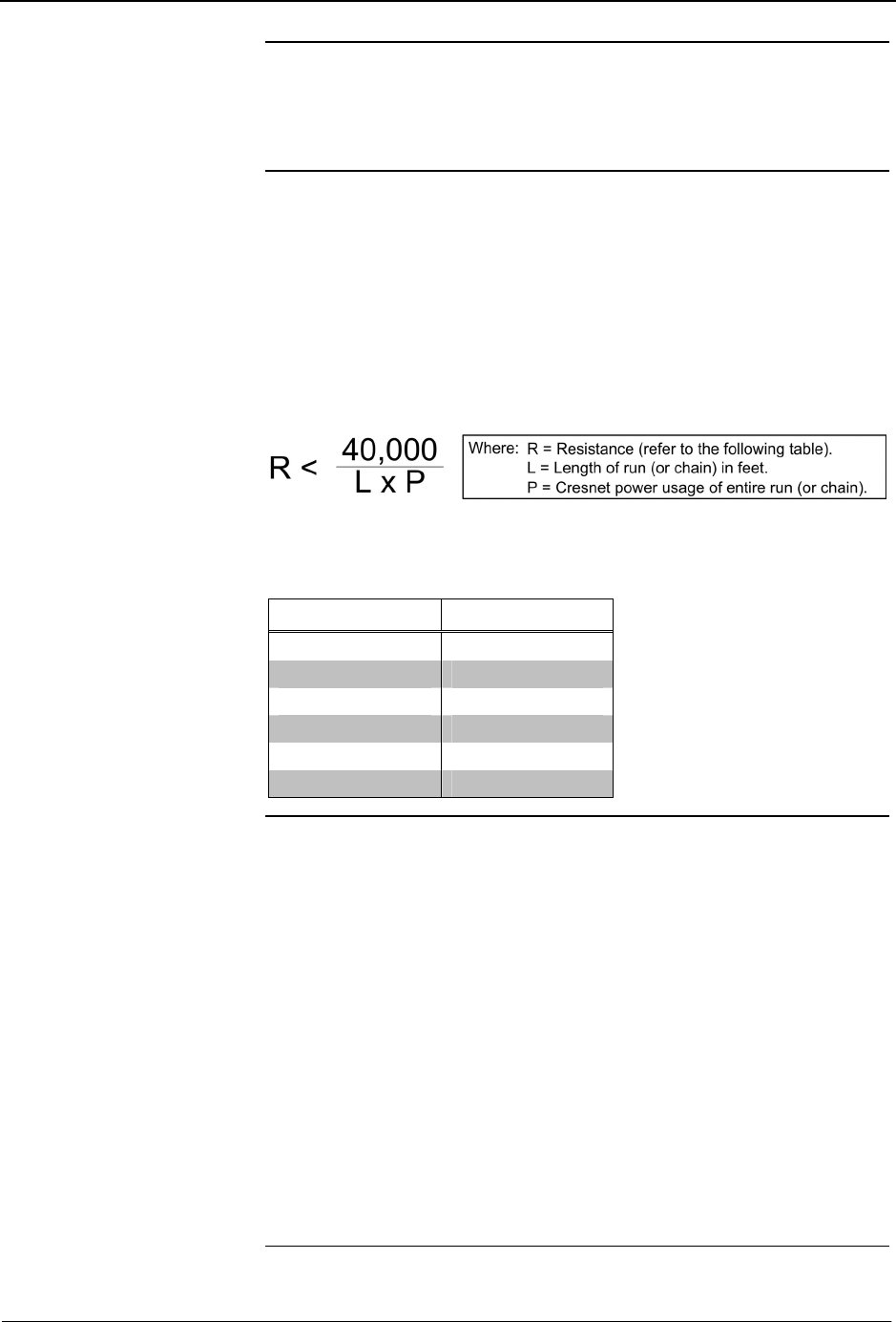
Resistance Equation
The required wire gauge should be chosen such that the resistance value is less
than the value calculated in the resistance equation. Refer to the following table.
Wire Gauge Values
RESISTANCE WIRE GAUGE
4 16
6 18
10 20
15 22
13 Doubled CAT5
8.7 Tripled CAT5
NOTE: All Cresnet wiring must consist of two twisted pairs. One twisted pair
is the +24V conductor and the GND conductor, and the other twisted pair is the
Y conductor and the Z conductor.
NOTE: When daisy-chaining Cresnet units, strip the ends of the wires carefully
to avoid nicking the conductors. Twist together the ends of the wires that share a
pin on the network connector, and tin the twisted connection. Apply solder only
to the ends of the twisted wires. Avoid tinning too far up the wires or the end
becomes brittle. Insert the tinned connection into the Cresnet connector and
tighten the retaining screw. Repeat the procedure for the other three conductors.
NOTE: For additional information on video connections over CAT5, refer to
the latest version of the Crestron CAT5 Wiring Reference Guide (Doc. 6137)
which is available from Crestron website (http://www.crestron.com/manuals).
NOTE: For larger networks (i.e., greater than 28 network devices), it may be
necessary to add a Cresnet Hub/Repeater (CNXHUB) to maintain signal quality
throughout the network. Also, for networks with lengthy cable runs or varying
types of network devices, it may be desirable to add a hub/repeater after only 20
network devices.
Operations & Installation Guide – DOC. 6338 FlipTop Control Center with Cresnet
®
: C2N-FTB • 7