
User Manual


Two-Way RF Transceiver Crestron STRFGWX
6 •• Two-Way RF Transceiver: STRFGWX Operations Guide - DOC. 5811A
Setup
Network Wiring
NOTE: If making category 5 connections to the Cresnet peripherals, refer to the
latest revision of the Cresnet Mini Network CAT 5 Interconnect Drawing (Doc.
5819). This document can be obtained from the Downloads page (CABLES and
MANUAL Libraries) of Crestron’s website (www.crestron.com). Search for
CAT5.PDF. New users are required to register in order to obtain access to the site.
NOTE: Review the latest revision of the Network Modular Cable Requirements
(Doc. 5682). This document can be obtained from the Downloads page (CABLES
and MANUAL Libraries) of Crestron’s website (www.crestron.com). Search for
MODULAR.PDF.
When calculating the wire gauge for a particular Cresnet run, the length of the run
and the load factor of each network unit to be connected must be taken into
consideration. If Cresnet units are to be daisy-chained on the run, the load factor of
each unit to be daisy-chained must be added together to determine the load factor of
the entire chain. If the unit is a home-run from a Crestron system power supply
network port, the load factor of that unit is the load factor of the entire run. The
length of the run in feet and the load factor of the run should be used in the resistance
equation on the next page to calculate the value on the right side of the equation.
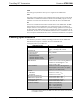
Resistance Equation
R = Resistance (refer to next table).
L = Length of run (or chain) in feet.
LF = Load factor of entire run (or chain).
R <
L x LF
40,000
Where:
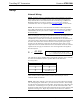
The required wire gauge should be chosen such that the resistance value is less than
the value calculated in the resistance equation. Refer to the table below.
Wire Gauge Values
RESISTANCE (R) WIRE GAUGE
4 16
6 18
10 20
15 22
13 24 (Double-CAT 5)
NOTE: All Cresnet wiring must consist of two twisted-pairs. One twisted pair is the
+24V conductor and the GND conductor and the other twisted pair is the Y
conductor and the Z conductor.
NOTE: When daisy-chaining Cresnet units, always twist the ends of the incoming
wire and outgoing wire which share a pin on the network connector. After twisting
the ends, tin the twisted connection with solder. Apply solder only to the ends of the
twisted wires. Avoid tinning too far up the wires or the end becomes brittle. After
tinning the twisted ends, insert the tinned connection into the Cresnet connector and
tighten the retaining screw. Repeat the procedure for the other three conductors.