
User Manual


Two-Way RF Transceiver Module Crestron CWDHR
4 Two-Way RF Transceiver Module: CWDHR Operations Guide - DOC. 7657A
Setup
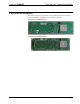
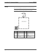
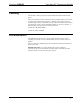
Refer to the following diagram. P1 is the interface port. J1 is the antenna port.
NOTE: To prevent unit-to-unit RF interference, multiple modules operating at the
same frequencies should not be installed within 3-5 feet of each other.
P1 Pin out Signals
Pin # Signal Pin # Signal
1
+3.0V 2
JTDO
3
\JRST 4 JTDI
5
AGND 6 JTCK
7
JTMS 8 \RESET
9
PA4 / PTI_EN 10 PA5 / PTI_DATA