
Operations Guide


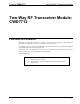
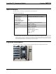
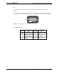
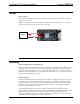
Table Of Contents

Crestron CWD7712 Two-Way RF Transceiver Module
Operations Guide - DOC. 7019A Two-Way RF Transceiver Module: CWD7712 • 3
Ports
The module contains a 10-pin connector. Refer to the diagrams and descriptions that follow.
Power/I-O
The 10 pin connector provides power to the module as well as communications between the module
and wired devices. Refer to the following table for pin assignments of the module interface connector.
9
10
1
2
NO
TE: Pin 9 provides power to the circuit card.
Power/I-O Pinout Signals
Pin # Signal Pin # Signal
1
ZERO_X/PWM 6 FILTERED_ZERO_X_
2
RELAY_ON/FET_A 7 GND
3
CURRENT_SENSE 8 REMOTE_RX
4
RELAY_OFF/FET_B 9 +4V (in)
5
FAULT 10 +3.3V (out)