
User Manual


Two-Way RF Transceiver Module Crestron CWD7134
4 Two-Way RF Transceiver Module: CWD7134 Operations Guide - DOC. 7497B
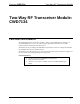
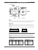
CWD7134 Detail Views
Ports
The module contains a 4-pin male header for application power and a 8-pin male header for application
I/O. A 10-pin debug header is also provided. Refer to the diagrams and descriptions that follow.
Power/I-O
The 8-pin male connector provides power to the module as well as the communication between the
module and wired devices. Refer to the following table for pin assignments of the module interface
connector.
The 4-pin male connector provides power connections for the wired devices connected to the module.
NOTE: Pins 3 and 4 on the 8-pin connector provide power to the module.
NOTE: Pins 1 and 4 on the 4-pin connector are connected to pins 1 and 2 on the 8-pin connector
through protection circuitry. These pins act as a pass through for power to be supplied to the wired
devices.
Power/I-O Pinout Signals
8-Pin Connector 4-Pin Connector
Pin # Signal Pin # Signal Pin # Signal
1
24V 5 PB1/TXD 1 24V
2
GND 6 PB2/RXD 2 No Connect
3
GND 7 PC7 OUTPUT 3 No Connect
4
5V 8 PC6 INPUT 4 GND