
User Manual


Crestron CWD7083 Two-Way RF Transceiver Module
Operations Guide - DOC. 7402A Two-Way RF Transceiver Module: CWD7083 3
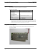
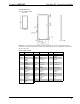
CWD7083 Detail Views
Power/I-O – An edge connector provides power to the module as well as serial communications
between the module and wired devices. Refer to the following table for pin assignments of the module
interface connector.
Power/I-O Pinout Signals
Pin # Signal Pin # Signal Pin # Signal
1 +5v 12-16 Reserved 29 Reserved
GPIO
2 GND 17-20 GND 30 SCLK
3 GPIO
PWMA
21 UART RX 31 MOSI
4 GPIO
PWMB
22 UART TX 32 MISO
5 Reserved
GPIO
23 Reserved
GPIO
33 CONFIG1
6 Reserved
GPIO
24 RESET 34 CONFIG2
7 Reserved
GPIO
25 Reserved
ADC1
35 Reserved
GPIO
8 Reserved
GPIO
26 Reserved
ADC2
36 GND
9 Reserved
GPIO
27 Reserved
ADC3
62 GND
10 Reserved
GPIO
28 GND 63 +5v
11 GND