
User Manual


Crestron CWD7041 Two-Way RF Transceiver Module with Integral Antenna
Operations Guide - DOC. 7263A Two-Way RF Transceiver Module with Integral Antenna: CWD7041 3
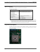
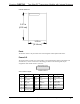
CWD7041 Detail View
Ports
The module contains a 25-pin header. Refer to the diagrams and descriptions that follow.
Power/I-O
The 25-pin header provides power to the module, serial communications between the module and
wired devices, as well as connections to the debug port. Refer to the following table for pin
assignments of the module interface connector.
Power/I-O Pinout Signals
Pin # Signal Pin # Signal Pin # Signal
1 SPI MISO 10 RESET 18 PB6
2 PB4 11 PA6 19 PC2 / JTDO
3 SPI_MISO 12 +3.3V 20 PB7
4 PB3 13 PB1 21 PC3 / JTDI
5 SPI_CLK 14 GROUND 22 PC0 / JRST
6 PA7 15 PB2 23 PC4 / JTMS
7 PA4 16 PB5 24 PC1
8 PC7 17 JTCK 25 PB0
9 PA5/PTI_DATA
1.57 in
(4.00 cm)
1.25 in
(3.18 cm)