
User Manual


Crestron CWD6790 Two-Way RF Transceiver Module
Operations Guide - DOC. 7019A Two-Way RF Transceiver Module: CWD6790 • 3
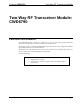
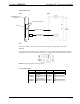
CWD6790 Detail Views
SIDE BACK
Antenna
Antenna Feed Pogo-pins
10-pin Mating
Connector
PCB with Radio
Plastic Button Frame
with Antenna
Ports
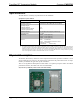
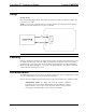
The module contains a 10-pin connector. Refer to the diagrams and descriptions that follow.
Power/I-O
The 10 pin connector provides power to the module as well as communications between the module
and wired devices. Refer to the following table for pin assignments of the module interface connector.
NOTE: Pin 1 provides power to the circuit card.
Power/I-O Pinout Signals
Pin # Signal Pin # Signal
1
+5V 6 REMOTE_B/CONFIG
2
TRIAC/RELAY 7 GND
3
ZERO_X 8 3.3V
4
REMOTE_A/RELAY 9 GND
5
GND 10 GND