
User Manual


Two-Way RF Transceiver Module Crestron CWD6782
4 • Two-Way RF Transceiver Module: CWD6782 Operations Guide - DOC. 7069A
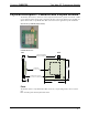
Power/I-O
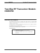
The 25pin D-SUB male connector provides power to the module as well as the communication
between the module and wired devices.
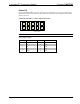
Refer to the following table for pin assignments of the module interface connector.
1
108
97
6
5
4
3
2
17151311
18
232119
161412
25
242220
NOTE: Pin 22 and 24 provides power to the circuit card.
Power/I-O Pinout Signals
Pin # Signal Pin # Signal
1
SPI_CLK 2 SPI_MISO
3
GP12 4 SPI_MOSI
5
GP4/PT1 EN 6 GP11/TM2IC_A
7
GP5/PT1_DATA 8 GND
9
GP6/ADC2 10 GND
11
GP7/ADC3 12 GND
13
GP8 14 GND
15
GP9/TXD 16 GND
17
GP10/RXD 18 GND
19
GP16/TM1OC_B 20 GND
21
GP15/TM1OC_A 22 +5V
23
GP14/TM2OC_B 24 +5V
25
GP13/TM2OC_A