
User Manual


Crestron CWD6782 Two-Way RF Transceiver Module
Operations Guide - DOC. 7069A Two-Way RF Transceiver Module: CWD6782 • 3
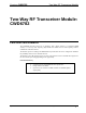
Physical Description – CWD6782 with a SMD Antenna
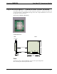
The module, shown below, consists of various components attached to a printed circuit board. The
circuit board attaches an intended SMD mounting antenna while a 25pin D-SUB Male connector is for
the application-specific installation.
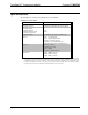
Physical View of CWD6782 (SMD antenna)
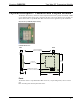
CWD6782 Detail Views
SIDE BACK
P
C
B
RF SHIELD
SMD ANTENNA
D-SUB 25 PIN
MALE CONNECTOR
PCB WITH RADIO
1.80 inch
4.572 cm
1.90 inch
4.83 cm
0.45 inch
1.143 cm
PIN 1
PIN 25
PIN 24
PIN 2
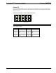
P1
Ports
The module contains a 25pin D-SUB Male connector and a 10-pin debug header.
Refer to the diagrams and descriptions that follow.