
User Manual


Crestron CWD6782 Two-Way RF Transceiver Module
Operations Guide - DOC. 7069A Two-Way RF Transceiver Module: CWD6782 • 7
Setup
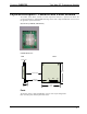
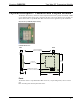
Refer to the hookup diagram below, which shows the connections made to the module. Complete the
connections in any order.
NOTE: To prevent unit-to-unit RF interference, multiple modules operating at the same frequencies
should not be installed within three to five feet of each other.
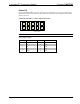
Hardware Hookup
PIN 1
PIN 25
PIN 24
PIN 2
HOST PCB
PIN 1
PIN 24
PIN 25
PIN 2
+5V
CONTROL
P1
J5
CWD6782
RADIO MODULE
HOST PCB
PIN 1
PIN 10
PIN 9
PIN 2
PIN 1
PIN 10
PIN 9
PIN 2
RF SHIELD
P2
J3
CABLE ASSY,
2.5 INCH
5 PIN DBL ROW
FEMALE, CONNC.
Labeling
If the FCC identification number is not visible when the module is installed inside another device, then
the outside of the device into which the module is installed must also display a label referring to the
enclosed module. This exterior label can use wording such as the following: “Contains Transmitter
Module FCC ID: EROCWD6782” or “Contains FCC ID: EROCWD6782.” Any similar wording that
expresses the same meaning may be used.