
User's Manual


Crestron CWD6590 Two-Way RF Transceiver Module w/Antenna
Operations Guide - DOC. 6859A Two-Way RF Transceiver Module w/Antenna: CWD6590 • 3
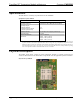
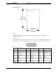
CWD6590 Detail Views
1.90 in
(4.83 cm)
1.25 in
(3.18 cm)
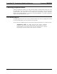
Ports
The module contains a 25-pin header and a 10-pin debug header. Refer to the diagrams and
descriptions that follow.
Power/I-O
The 25 pin header provides power to the module as well as serial communications between the module
and wired devices. Refer to the following table for pin assignments of the module interface connector.
Power/I-O Pinout Signals
Pin # Signal Pin # Signal Pin # Signal
1
SPI CLK 10 GROUND 19 GP16
2
SPI MISO 11 GP7 20 GROUND
3
GP12 12 GROUND 21 GP15
4
SPI MOSI 13 GP8 22 +3.3V
5
GP4 14 GROUND 23 GP14
6
GP11 15 GP9 24 +3.3V
7
GP5 16 GROUND 25 GP13
8
GROUND 17 GP10
9 GP6 18 GROUND
24681012141618202224
25 23 21 19 17 15 13 11 9 7 5 3 1