
User Manual


Crestron MNET-CWD1012 Two-Way RF Transceiver Module
Hardware Guide - DOC. 6351 Two-Way RF Transceiver Module: MNET-CWD1012 • 3
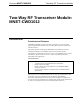
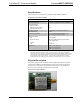
MNET-CWD1012 Detail Views
Ports
The module contains two ports. Refer to the diagrams and descriptions that follow.
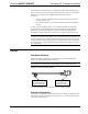
Power/I-O
A Crestron JDSM31M-1 31 pin, male, SMT interface connector provides power to
the module as well as serial communications between the module and wired devices.
The mating connector is Crestron part number JDSM31F-1, 31 pin, female, SMT
connector. Refer to the following table for pin assignments of the module interface
connector.
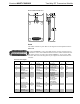
Power/I-O Pinout Signals
Pin # Signal Pin # Signal Pin # Signal Pin # Signal
1 GND 9 Reserved
No Connection
19 Reserved
No Connection
27 +5V
2 GND 10 Reserved
No Connection
20 SETUP Switch IN
(Active Low)
28 GND
3 Reserved
No Connection
11 Reserved
No Connection
21 Reserved
No Connection
29 +5V
4 MODULE
SERIAL OUT
12 Reserved
No Connection
22 RF Module
Status Out
(High=Connectio
n Active)
30 GND
5 MODULE
SERIAL IN
15 Reserved
No Connection
23 RF Module
SETUP Status
Out (High =
Setup Mode)
31 GND
6 No Connection 16 Reserved
No Connection
24 No Connection
7 RF Module
/RESET Input
(Active Low)
17 Reserved
No Connection
25 +5V
8 Reserved
No Connection
18 Reserved
No Connection
26 GND