
User Manual


Two-Way RF Transceiver Module Crestron CWD07343
4 Two-Way RF Transceiver Module: CWD07343 Operations Guide - DOC. 7649A
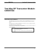
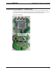
CWD07343 Detail Views
LEDINDICATOR
USERBUTTONS
RFSHIELD
SMDANTENNA
24VFEEDTHRU
CONNECTION
5VANDIO
CONNECTION
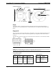
0.576in
1.93in
1.95in
Ports
The module contains a 4-pin male header for application power and a 10-pin female header for
application I/O. A 10-pin debug header is also provided. Refer to the diagrams and descriptions that
follow.
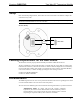
Power/I-O
The 10-pin female connector provides power to the module as well as the communication between the
module and wired devices. Refer to the following table for pin assignments of the module interface
connector.
The 4-pin male connector provides power connections for the wired devices connected to the module.
Pin1
Pin4
Pin1
Pin10
NOTE: Pins 1 and 2 on the 10-pin connector provide power to the module.
NOTE: Pins 1 and 4 on the 4-pin connector are connected to pins 3/5 and 7/9 on the 10-pin connector.
These pins act as a pass through for power to be supplied to the wired devices.
Power/I-O Pinout Signals
10-Pin Connector 4-Pin Connector
Pin # Signal Pin # Signal Pin # Signal
1
GND 2 5V 1 24V
3
24V 4 PB/6ADC1 (0.5x) 2 No Connect
5
24V 6 PB7/ADC2 (0.5x) 3 No Connect
7
PGND 8 PB1/TXD 4 PGND
9
PGND 10 PB2/RXD