
User Manual


Crestron CWD07234 Two-Way RF Transceiver Module
Operations Guide - DOC. 7520A Two-Way RF Transceiver Module: CWD07234 5
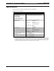
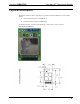
Power/I-O
The 11-pin header double row connector provides power to the module as well as the communications
between the module and wired devices. Refer to the following table for pin assignments of the module
interface connector.
Power/I-O Pinout Signals
Pin # Signal Pin # Signal
1 AGND 2 JTCK
3 RESET_N 4 WAKE_N
5 JTRS_N 6 HOST_INT_N/PB2_RXD
7 JTDI 8 PB1/TXD
9 JTDO 10 PA6
11 JTMS 12 +VIN
13 PA7 14 PA5/PT1_DATA
15 PA4/PT1_EN 16 PB3
17 SPI_MISO 18 EE_CS_N
19 SPI_SSO_N 20 SPI_MOSI
21 SPI_CLK 22 AGND
Labeling Requirements for the Host Device
The host device shall be properly labeled to identify the modules within the host device.
The FCC and Industry Canada certification label of a module shall be clearly visible at all times when
installed in the host device, otherwise the host device must be labeled to display the FCC and Industry
Canada certification numbers of the module, proceeded by the words “Contains Transmitter Module”,
or the word “Contains”, or similar wording expressing the same meaning as follows:
Contains FCC ID: EROCWD07234
Contains IC: 5683C-CWD07234
Documentation
The OEM integrator has to be aware not to provide information to the end user regarding how to install
or remove this RF module in the users manual of the end product.
The users manual for OEM integrators must include the following information in a prominent location
“IMPORTANT NOTE: To comply with FCC RF exposure compliance
requirements, the antenna used for this transmitter must be installed to provide a
separation distance of at least 20 cm from all persons and must not be co-located
or operating in conjunction with any other antenna or transmitter.”