Crestron SPK-6L Speaker Kit for Isys® TPS-6L Wall Mount Touchpanel Installation Guide
Speaker Kit Crestron SPK-6L Contents Speaker Kit: SPK-6L 1 Description................................................................................................................................. 1 Setup .......................................................................................................................................... 2 Supplied Hardware ...................................................................................................... 2 Installation .......................
Crestron SPK-6L Speaker Kit Speaker Kit: SPK-6L Description The SPK-6L is a speaker option for the Isys® TPS-6L Wall Mount Touchpanel. Adding the SPK-6L provides amplification of external AV sources, and supports programmable intercom functionality in combination with the touchpanel's built-in microphone. Refer to the latest version of the TPS-6L Operation & Installation Guide (Doc. 6556) for information on using the SPK-6L. The manual is available from the Crestron website (www.crestron.com/manuals).
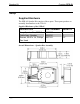
Speaker Kit Crestron SPK-6L Setup Supplied Hardware The SPK-6L Speaker Kit consists of three parts. These parts produce an assembly that attaches to the TPS-6L. Supplied Hardware of the SPK-6L DESCRIPTION PART NUMBER QUANTITY Assy, Speaker Box, TPS-6L Cable Assy, Speaker Screws, 04-40 x 1/4, Phillips, Pan Head 4505027 4504781 2007161 1 1 12* * Two extra screws are provided as spares. Overall Dimensions – Speaker Box Assembly 2 • Speaker Kit: SPK-6L Installation Guide – DOC.
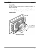
Crestron SPK-6L Speaker Kit Installation The only tool required and not supplied is a #2 Phillips screwdriver. To install the Speaker Kit: 1. Orient the speaker assembly as shown in the following illustration. Use a #2 Phillips screwdriver and attach the speaker to the rear of the touchpanel with four supplied screws. Attaching Speaker Installation Guide – DOC.
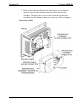
Speaker Kit Crestron SPK-6L 2. Refer to the following illustration and plug the two-conductor speaker cable into the mating connector on the speaker box assembly. Then plug the six-wire cable from the speaker box assembly into the mating connector on the rear of the touchpanel. Connecting Cables 4 • Speaker Kit: SPK-6L Installation Guide – DOC.
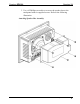
Crestron SPK-6L Speaker Kit 3. Use a #2 Phillips screwdriver to secure the speaker box to the touchpanel with six supplied screws. Refer to the following illustration. Attaching Speaker Box Assembly Installation Guide – DOC.
Speaker Kit Crestron SPK-6L Resources Industry Compliance As of the date of manufacture, the SPK-6L has been tested and found to comply with specifications for CE marking and standards per EMC and Radiocommunications Compliance Labelling. NOTE: This device complies with part 15 of the FCC rules.
Crestron SPK-6L Speaker Kit Reference Documents The latest version of all documents mentioned within the guide can be obtained from the Crestron website (www.crestron.com/manuals). This link will provide a list of product manuals arranged in alphabetical order by model number. List of Related Reference Documents DOCUMENT TITLE TPS-6L Isys® 5.
Speaker Kit Crestron SPK-6L Return and Warranty Policies Merchandise Returns / Repair Service 1. No merchandise may be returned for credit, exchange or service without prior authorization from CRESTRON. To obtain warranty service for CRESTRON products, contact an authorized CRESTRON dealer. Only authorized CRESTRON dealers may contact the factory and request an RMA (Return Merchandise Authorization) number.
Crestron SPK-6L Speaker Kit This page is intentionally left blank. . Installation Guide – DOC.
Crestron Electronics, Inc. 15 Volvo Drive Rockleigh, NJ 07647 Tel: 888.CRESTRON Fax: 201.767.7576 www.crestron.com Installation Guide – DOC. 6625A (2018883) 11.07 Specifications subject to change without notice.