Crestron QM-MD4x2 QuickMedia Distribution Center Operations Guide
This document was prepared and written by the Technical Documentation department at: Crestron Electronics, Inc. 15 Volvo Drive Rockleigh, NJ 07647 1-888-CRESTRON All brand names, product names and trademarks are the property of their respective owners. ©2004 Crestron Electronics, Inc.
Crestron QM-MD4x2 QuickMedia Distribution System Contents QuickMedia Distribution System: QM-MD4x2 1 Introduction ............................................................................................................................... 1 Features and Functions ................................................................................................ 1 Applications.................................................................................................................
Crestron QM-MD4x2 QuickMedia Distribution System QuickMedia Distribution System: QM-MD4x2 Introduction Features and Functions The Crestron® QuickMedia Distribution System, QM-MD4x2 (hereinafter referred to as MD4x2) is part of the Crestron MediaManager™ line of network devices, room control systems, and signal routing solutions.
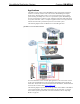
QuickMedia Distribution System Crestron QM-MD4x2 Applications The MD4x2 is part of the Crestron MediaManager line of integrated presentation solutions. It is ideally suited to work with Crestron’s MediaManager wall plate media centers, FlipTop media centers, receivers and control processors to allow quick switching of multiple A/V sources in a presentation system.
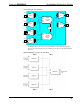
Crestron QM-MD4x2 QuickMedia Distribution System Functional Diagram of the QM-MD4x2 IN 1 R G B H V DA1 QM Front End 1 VID 1 VID 2 VID 3 IN 2 R G QM B Front End H 2 V DA2 VIDEO 4X2X5 MUX VID 4 5-Layer Crosspoint Cresnet Control IN 3 R G B H V DA3 QM Front End 3 DA1 DA2 DA3 IN 4 R G QM B Front End H 4 V DA4 DA4 R G B QM Line Out 1 H V DA OUT 1 R G B QM Line H Out 2 V DA OUT 2 DIGITAL AUDIO 4X2X1 MUX 1-Layer Crosspoint An MD4x2 can be cascaded with a second MD4x2 or other QM-MD switching
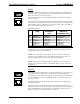
QuickMedia Distribution System Crestron QM-MD4x2 Specifications Specifications for the QM-MD4x2 are listed in the following table. QM-MD4x2 Specifications SPECIFICATION DETAILS Power Requirements 11 Watts (0.46 Amp @ 24 VDC) Default Net ID 07 Control System Update Files 2-Series Control System 1, 2 Version C2-V3.093.
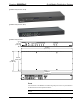
Crestron QM-MD4x2 QuickMedia Distribution System QM-MD4x2 Physical View (Front) QM-MD4x2 Physical View (Rear) QM-MD4x2 Physical Views 1.70 in (4.32 cm) 17.03 in (43.24 cm) 6.44 in (16.35 cm) 6.64 in (16.86 cm) 16.92 in (42.98 cm) 24 Y Z G 1 24 Y Z G 2 24 Y Z G 24 Y Z G 3 4 24 G 24 G QM QM IN OUT 24 Y Z G 24 Y Z G 1 2 Ports All connections to the MD4x2 are made through the ports on the rear panel. Refer to the illustrations and descriptions that follow.
QuickMedia Distribution System Crestron QM-MD4x2 QM IN The MD4x2 contains four QM ports for connecting QM sources. Each QM port has an RJ-45 connector for QM signals and a corresponding 4-position mini-terminal block connector for Cresnet control signals. 24 Y Z G For wiring information, refer to “QuickMedia Wiring” on page 10 and “Network Wiring” on page 9.
Crestron QM-MD4x2 QuickMedia Distribution System QM POWER The MD4x2 contains two 2-position terminal block connectors that provide 24VDC power to the Cresnet ports on each of the QM ports. Power to the QM power ports can be supplied by the Crestron C2N-SPWS300 External 300 Watt Power Supply or the Crestron CN-PWS75 External 75 Watt Power Supply. For more information, refer to “Hardware Hookup” on page 16.
QuickMedia Distribution System Crestron QM-MD4x2 While in the system mode, pressing V will indicate where the video portion of a signal is routed. For more information on the MD4x2’s operating modes, refer to “Operating Modes” on page 28. SYS (System) Press this button to set the MD4x2 to the system mode. When the accompanying LED is illuminated, all switching functions are controlled by the Crestron control system.
Crestron QM-MD4x2 QuickMedia Distribution System Industry Compliance As of the date of manufacture, the MD4x2 has been tested and found to comply with specifications for CE marking and standards per EMC and Radiocommunications Compliance Labelling (N11785). NOTE: This device complies with part 15 of the FCC rules.
QuickMedia Distribution System Crestron QM-MD4x2 each network unit to be daisy-chained must be added together to determine the power factor of the entire chain. The length of the run in feet and the power factor of the run should be used in the following resistance equation to calculate the value on the right side of the equation. Resistance Equation R < 40,000 L x PF Where: R = Resistance (refer to table below). L = Length of run (or chain) in feet. PF = Power factor of entire run (or chain).
Crestron QM-MD4x2 QuickMedia Distribution System CRESCAT-QM Cable NOTE: Do not untwist the two wires in a single pair for more than 1/3-1/2” (0.84 – 1.27 cm) when making a connection. The twists are critical to canceling out interference between the wires.
QuickMedia Distribution System Crestron QM-MD4x2 The pin assignments for Crescat-QM, CAT5, CAT5E, and CAT 6 wiring are based on the EIA/TIA 568B RJ-45 Jack standard. RJ-45 QuickMedia Connector Pin 1 To determine which pin is number 1, hold the cable so that the end of the eight-pin modular jack is facing you, with the clip down and the copper side up. When looking down at the copper connections, pin 1 is on the far right. The following table lists the pin assignments on the RJ-45 connector.
Crestron QM-MD4x2 QuickMedia Distribution System control system to recognize a network device via its serial number, which is stored in the device’s memory. This method does not require that any devices be disconnected from the network; Net IDs may be set with the entire Cresnet system intact. This method requires the use of the Crestron Viewport version 3.35 or later. Use the appropriate method to set the Net ID. Method A (Cresnet address-settable ID) 1.
QuickMedia Distribution System Crestron QM-MD4x2 “Set Net ID by TSID” Window 5. Enter either the serial number or TSID number of the device that requires a change. The list scrolls to and highlights the device listing. The listing should show the device’s default Cresnet ID (a.k.a. Net ID). 6. Enter the Cresnet ID that the device should be set to and click OK. The number you enter should appear on the list. CAUTION: This function does not prevent you from setting duplicate IDs.
Crestron QM-MD4x2 QuickMedia Distribution System 3. Enter the serial number or TSID number as instructed; press the appropriate button to obtain the corresponding number. NOTE: Enter serial numbers, including spaces, exactly as they appear on the unit label. Alpha characters in serial numbers or TSID numbers may be entered in upper or lower case.
QuickMedia Distribution System 4. Crestron QM-MD4x2 Repeat procedure (steps 1 through 3) to attach the remaining ear to the opposite side. Stacking Four "feet" are provided with the MD4x2 so that if the unit is not rack mounted, the rubber feet can provide stability when the unit is placed on a flat surface or stacked. These feet should be attached prior to the hookup procedure. Refer to the illustration below for placement of the feet.
Crestron QM-MD4x2 QuickMedia Distribution System The required 24 VDC power for the QM inputs and QM outputs can be supplied in a variety of ways. The following wiring diagram suggests one method of applying 24 VDC power to the QM ports. In this configuration, the C2N-SPWS300 can supply up to 75 watts of power to the QM inputs and QM outputs to ensure that sufficient power is available for QM devices that are connected to the MD4x2. The C2NSPWS300 can also supply the power required by the MD4x2.
QuickMedia Distribution System Crestron QM-MD4x2 Earliest Version Software Requirements for the PC NOTE: Crestron recommends that you use the latest software to take advantage of the most recently released features. The latest software is available from the Downloads | Software Updates section of the Crestron website (www.crestron.com). The following are the earliest useable software version requirements for the PC: • SIMPL Windows version 2.05.22 or later with Library Update 292 or later.
Crestron QM-MD4x2 QuickMedia Distribution System Expanded QM-RMCRX System Tree C2Net-Device Slot in Configuration Manager To incorporate an MD4x2 into the system, drag the QM-MD4x2 from the Cresnet Control Modules | QM Series folder of the Device Library and drop it in System Views. The QM-RMCRX system tree displays the QM-MD4x2 in Slot 5, with a default Net ID of 07 as shown in the following illustration.
QuickMedia Distribution System Crestron QM-MD4x2 NOTE: This procedure sets the Net ID for the MD4x2 in the program only. It does not automatically set the Net ID for the MD4x2 itself. SIMPL Windows automatically changes Net ID values of a device added to a program if a duplicate device or a device with the same Net ID already exists in the program. Always ensure that the hardware and software settings of the Net ID match. For Net ID hardware setting details, refer to “Identity Code” on page 12.
Crestron QM-MD4x2 QuickMedia Distribution System QM-MD4x2 Analog Input Signal Descriptions INPUT DESCRIPTION VideoOut1 and VideoOut2 Select the QM video source to be switched to the indicated QM output. Valid analog values range from 0 (for no source) through 4, and correspond to the QM 1 and QM4 inputs. Thus to route a video source from QM In 4 to QM Out 2, initialize VideoOut2 to 4d. Select the QM audio source to be switched to the indicated QM output.
QuickMedia Distribution System Crestron QM-MD4x2 QM-MD4x2 Digital Output Signal Descriptions OUTPUT LocalMode-FB DESCRIPTION Indicates that the MD4x2 has been put into local mode via the LOCAL button on the unit. The output remains high for as long as the unit is in local mode. The analog feedback outputs will report the audio/video sources present at each QM output regardless of the mode.
Crestron QM-MD4x2 QuickMedia Distribution System Uploading and Upgrading Assuming a PC is properly connected to the entire system, Crestron programming software allows the programmer to upload programs and projects after their development to the system and network devices. However, there are times when the files for the program and projects are compiled and not uploaded. Instead, compiled files may be distributed from programmers to installers, from Crestron to dealers, etc.
QuickMedia Distribution System Crestron QM-MD4x2 Typical Connection Diagram when Uploading 1. Open the Crestron Viewport. Either launch the stand-alone version of Viewport or start SIMPL Windows and from the menu bar, select Tools | Viewport. 2. Refer to the following figure after this step. From the Viewport menu, select Setup | Communications settings (alternatively, press Alt+D) to open the “Port Settings” window. Setup | Communications Settings Command 3. Select RS-232 as the connection type.
Crestron QM-MD4x2 QuickMedia Distribution System “Port Settings” Window NOTE: The parameters shown in the illustration above are the port settings for a 2Series control system. Consult the Operations Guide for the control system being used for exact parameter selection. 4. To verify communication, select Diagnostics | Establish Communications (Find Rack). This should display a window that gives the COM port and baud rate.
QuickMedia Distribution System Crestron QM-MD4x2 File Transfer | Send Program Command 3. The “Send Program” window appears, as shown after this step. Click Browse, locate the compiled file (.spz for PRO2) and click Open. This will display the program's header information and enable one or both of the What to Send check boxes. If the program does not contain any SIMPL+ modules, only the SIMPL Program check box will be enabled.
Crestron QM-MD4x2 QuickMedia Distribution System 2. As shown after this step, select File Transfer | Update Network Device Firmware… from the Viewport menu bar. File Transfer | Update Network Device Firmware… Command 3. As shown after this step, select the Net ID of the MD4x2 and then click OK. The “Open” window appears (refer to the subsequent graphic).
QuickMedia Distribution System Crestron QM-MD4x2 Operation Operating Modes The MD4x2 operates in either the system mode or the local mode. When operating in the system mode, all switching functions are controlled by the control system. Additionally, signal routing information can be viewed using the front panel controls of the MD4x2. When operating in the local mode, all switching functions are controlled by the buttons on the front panel.
Crestron QM-MD4x2 QuickMedia Distribution System 3. Select the input to be switched by pressing its corresponding button. 4. Select the destination(s) where the signal is to be switched. If an output’s LED is lit, the input signal will be routed there. To disable a routing destination, press the output button again. The LED will turn off. NOTE: If a button-press causes a change to the current switching schema, the ENTER LED will flash rapidly. 5. Press ENTER to enable the new signal routes.
QuickMedia Distribution System Crestron QM-MD4x2 Problem Solving Troubleshooting The following table provides corrective action for possible trouble situations. If further assistance is required, please contact a Crestron customer service representative. QM-MD4x2 Troubleshooting TROUBLE POSSIBLE CAUSE(S) CORRECTIVE ACTION PWR LED does not illuminate. MD4x2 is not receiving power. Verify that cables plugged into the NET ports are secure. NET LED does not illuminate. MD4x2 Net ID is not correct.
Crestron QM-MD4x2 QuickMedia Distribution System Future Updates As Crestron improves functions, adds new features, and extends the capabilities of the MD4x2, additional information may be made available as manual updates. These updates are solely electronic and serve as intermediary supplements prior to the release of a complete technical documentation revision. Check the Crestron website (www.crestron.com) periodically for manual update availability and its relevance.
QuickMedia Distribution System Crestron QM-MD4x2 Appendix: Serial Protocol All commands and responses are printable ASCII and are terminated with a (\x0D). The serial commands listed here are grouped into front panel functions, verbose mode functions, and switching/routing functions. NOTE: Multiple serial commands cannot be strung together. NOTE: When programming the MD4x2 using serial commands, digital and analog commands should not be used.
Crestron QM-MD4x2 QuickMedia Distribution System NOTE: The setting for the verbose mode is retained even after power to the MD4x2 is cycled. NOTE: Commands can be sent to the MD4x2 regardless of the status of the verbose mode. Verbose Mode Commands COMMAND R0\r R1\r R?\r FUNCTION Verbose mode off Verbose mode on Get verbose mode status When the state of the verbose mode changes to on, or if polled for status, the MD4x2 replies with one of the responses listed in the following table.
QuickMedia Distribution System Crestron QM-MD4x2 When the verbose mode is on and the routing status changes while the MD4x2 is in the system mode, or if the MD4x2 is polled for the status of an output, the MD4x2 replies with one of the responses listed in the following table. Switching/Routing Status Replies MESSAGE IxOyA\r IxOyV\r SA1V1A2V2\r DEFINITION New audio route if audio route has changed where x will be a two-digit number from 00 to 04 and y will be a two-digit number from 01 to 02.
Crestron QM-MD4x2 QuickMedia Distribution System Return and Warranty Policies Merchandise Returns / Repair Service 1. No merchandise may be returned for credit, exchange, or service without prior authorization from CRESTRON. To obtain warranty service for CRESTRON products, contact the factory and request an RMA (Return Merchandise Authorization) number. Enclose a note specifying the nature of the problem, name and phone number of contact person, RMA number, and return address. 2.
Crestron Electronics, Inc. 15 Volvo Drive Rockleigh, NJ 07647 Tel: 888.CRESTRON Fax: 201.767.7576 www.crestron.com Operations Guide – DOC. 6278 06.04 Specifications subject to change without notice.