Crestron CEN-SW-POE-5 5-Port Power over Ethernet Switch Installation Guide
This document was prepared and written by the Technical Documentation department at: Crestron Electronics, Inc. 15 Volvo Drive Rockleigh, NJ 07647 1-888-CRESTRON All brand names, product names and trademarks are the property of their respective owners. ©2008 Crestron Electronics, Inc.
Crestron CEN-SW-POE-5 5-Port Power over Ethernet Switch Contents 5-Port Power over Ethernet Switch: CEN-SW-POE-5 1 Introduction ............................................................................................................................... 1 Features and Functions ................................................................................................ 2 Specifications ..............................................................................................................
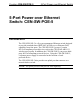
Crestron CEN-SW-POE-5 5-Port Power over Ethernet Switch 5-Port Power over Ethernet Switch: CEN-SW-POE-5 Introduction The CEN-SW-POE-5 is a five-port unmanaged Ethernet switch designed to provide standards-based IEEE 802.3af Power over Ethernet (PoE) capability from four ports. The CEN-SW-POE-5 powers Crestron 802.3af-compliant powered devices such as the CEN-WAP-ABG-1G wireless access point. In addition, the CEN-SW-POE-5 can power thirdparty 802.3af-compliant powered devices.
5-Port Power over Ethernet Switch Crestron CEN-SW-POE-5 Features and Functions • • • • Four 10BaseT/100BaseTX 802.3af PoE ports One 10BaseT/100BaseTX uplink port Autonegotiation of data transmission rate and duplex mode Auto MDI/MDI-X (Medium Dependent Interface/Medium Dependent Interface Crossover) operation • 3.2 Gbps switching fabric • Wall and rack mountable design Four 10BaseT/100BaseTX 802.3af PoE Ports Using 802.3af PoE technology, each of four 10BaseT/100BaseTX ports can provide power to an 802.
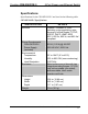
Crestron CEN-SW-POE-5 5-Port Power over Ethernet Switch Specifications Specifications for the CEN-SW-POE-5 are listed in the following table. CEN-SW-POE-5 Specifications SPECIFICATION Ethernet 10BaseT/100BaseTX, autoswitching, auto-negotiating, autodiscovery, full/half duplex; TCP/IP, UDP/IP, DHCP, IGMP; IEEE 802.3, 802.3u, 802.3x, and 802.
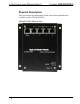
5-Port Power over Ethernet Switch Crestron CEN-SW-POE-5 Physical Description This section provides information on the connections and indicators available on your CEN-SW-POE-5. CEN-SW-POE-5 Physical View 4 • 5-Port Power over Ethernet Switch: CEN-SW-POE-5 Installation Guide – DOC.
Crestron CEN-SW-POE-5 5-Port Power over Ethernet Switch CEN-SW-POE-5 Overall Dimensions Front View 5.06 in (12.86 cm) 3.62 in (9.18 cm) Bottom View 1.17 in (2.97 cm) 4.66 in (11.82 cm) Installation Guide – DOC.
5-Port Power over Ethernet Switch Crestron CEN-SW-POE-5 CEN-SW-POE-5 Connectors & Indicators 1 2 3 4 5 6 • 5-Port Power over Ethernet Switch: CEN-SW-POE-5 Installation Guide – DOC.
Crestron CEN-SW-POE-5 5-Port Power over Ethernet Switch Connectors & Indicators # 1 CONNECTORS & INDICATORS Uplink AMBER LED 8 GREEN LED 1 DESCRIPTION (1) 8-wire RJ-45 connector with 2 LED indicators; 10BaseT/100BaseTX Ethernet port; Amber LED indicates 100BaseT link status; Solid Green LED indicates link status; Flashing Green LED indicates Ethernet activity. Connects to network hub or switch.
5-Port Power over Ethernet Switch Crestron CEN-SW-POE-5 Connectors & Indicators (Continued) # CONNECTORS & INDICATORS DESCRIPTION PoE (1-4) (4) 8-wire RJ-45 connectors with 2 LED indicators; 10BaseT/100BaseTX PoE ports for power and data; Amber LED indicates 100BaseT link status; Solid Green LED indicates link status; Flashing Green LED indicates Ethernet activity. Connect to 802.3af-compliant powered devices. Maximum PoE load per port: 15.
Crestron CEN-SW-POE-5 5-Port Power over Ethernet Switch Connectors & Indicators (Continued) # CONNECTORS & INDICATORS DESCRIPTION 4 48VDC (1) 4-pin power connector, 48 VDC power input (external power supply included). 5 * 1 3 2 4 Power 48VDC Connector Pin Assignments PIN DESCRIPTION 1 +48 VDC 2 +48 VDC 3 Ground 4 Ground (1) Yellow LED, indicates 48 VDC power supplied from the external power supply. Due to the inherent voltage drop over copper wire, a maximum of 12.
5-Port Power over Ethernet Switch Crestron CEN-SW-POE-5 Industry Compliance This product is Listed to applicable UL Standards and requirements by Underwriters Laboratories Inc. (E312979) As of the date of manufacture, the CEN-SW-POE-5 has been tested and found to comply with specifications for CE marking and standards per EMC and Radiocommunications Compliance Labelling. NOTE: This device complies with part 15 of the FCC rules.
Crestron CEN-SW-POE-5 5-Port Power over Ethernet Switch Setup Network Wiring When wiring the Ethernet network, use Category 5 (CAT5) wiring. CAT5 wiring is a twisted pair cable designed for Ethernet networks. These networks operate at speeds of up to 100 Megabits per second (Mbps) using the 100BaseT standard. For information on connecting Ethernet devices in a Crestron system, refer to the latest version of the Crestron e-Control® Reference Guide (Doc.
5-Port Power over Ethernet Switch Crestron CEN-SW-POE-5 Installation Ventilation The CEN-SW-POE-5 venting holes should not be obstructed under any circumstances. To prevent overheating, do not operate this product in an area that exceeds the environmental temperature range listed in the table of specifications. Rack Mounting The CEN-SW-POE-5 can be mounted to a front or rear rail of a rack using the supplied rack screws and washers.
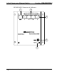
Crestron CEN-SW-POE-5 Wall Mounting 5-Port Power over Ethernet Switch The CEN-SW-POE-5 can be mounted to a wall. To mount the device to a wall, use the four supplied 3/16 x 1-1/4” pan head Phillips drywall screws (refer to the illustration below). Wall Mounting (4) Screws, 3/16 x 1¼” Phillips Pan Head Installation Guide – DOC.
5-Port Power over Ethernet Switch Crestron CEN-SW-POE-5 Hardware Hookup Make the necessary connections as called out in the illustration that follows this paragraph. Apply power after all connections have been made. When making connections to the CEN-SW-POE-5, note the following: • Use Crestron power supplies for Crestron equipment. • The included cable(s) cannot be extended.
Crestron CEN-SW-POE-5 5-Port Power over Ethernet Switch Problem Solving Troubleshooting The following table provides corrective action for possible trouble situations. If further assistance is required, please contact a Crestron customer service representative. CEN-SW-POE-5 Troubleshooting TROUBLE POSSIBLE CAUSE(S) Power LED does not illuminate. AC power cord is not properly connected to the external power supply or to the power outlet. DC power cord is not firmly plugged into the DC power jack.
5-Port Power over Ethernet Switch Crestron CEN-SW-POE-5 CEN-SW-POE-5 Troubleshooting (Continued) TROUBLE Green LED on Ethernet port does not illuminate. (Continued) POSSIBLE CAUSE(S) CORRECTIVE ACTION Network cable is not the proper length. Fault exists with the network cable. Port is not functioning. PoE LED does not illuminate. 10BaseT/100BaseTX compatible device is not 802.3af compliant and is not powered on. 10BaseT/100BaseTX compatible device is not 802.3af compliant.
Crestron CEN-SW-POE-5 5-Port Power over Ethernet Switch Reference Documents The latest version of all documents mentioned within the guide can be obtained from the Crestron website (www.crestron.com/manuals). This link will provide a list of product manuals arranged in alphabetical order by model number.
5-Port Power over Ethernet Switch Crestron CEN-SW-POE-5 Return and Warranty Policies Merchandise Returns / Repair Service 1. No merchandise may be returned for credit, exchange or service without prior authorization from CRESTRON. To obtain warranty service for CRESTRON products, contact an authorized CRESTRON dealer. Only authorized CRESTRON dealers may contact the factory and request an RMA (Return Merchandise Authorization) number.
Crestron CEN-SW-POE-5 5-Port Power over Ethernet Switch This page is intentionally left blank. Installation Guide – DOC.
Crestron Electronics, Inc. 15 Volvo Drive Rockleigh, NJ 07647 Tel: 888.CRESTRON Fax: 201.767.7576 www.crestron.com Installation Guide – DOC. 6694A (2021172) 08.08 Specifications subject to change without notice.