
Instruction manual
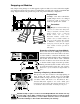
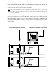

Swapping out Modules
Only jumper setting changes or module upgrades require modules to be removed from the amplifi-
er. Contact Crest Audio Customer Service for full details on module removal. The ‘General Module
Setup’ diagram indicates the general setup of the rear panel module/bay configuration.
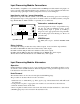
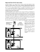
Required Tools
A Phillips screw driver. Should the
module jumpers need to be changed
or removed, a pair of long nose or
needle nose pliers is also useful.
Precautions
Amplifier is shown with the top
cut away for clarity only. Dangerous
voltages exist inside, and only a Crest
Audio-certified service technician
should remove the top cover!
Removable modules contain static-
sensitive devices; handle modules at
static-safe work stations! The amplifi-
er MUST be switched off and the
mains plug removed from the supply
before module removal operation is
undertaken.
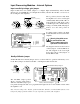
Removing or Replacing an Input Module.
Remove the four #8 3/8" Phillips pan head sheet
metal screws that secure the module to the chas-
sis. The module is connected electrically to the
amplifier via multi-pin ribbon cables. Unplugging
the module from the ribbon cable connectors
frees the module for removal. To insert the same
or another module, simply reverse this procedure,
making sure that any ribbon cable connectors are
properly and securely seated. Note: The amplifier
must not be operated without an Input module in
place.
Removing or Replacing a Network Module.
This process is the same as that for removing/replacing an
Input module. Be aware, though, that if an NC-NXS
Network module is being removed or replaced, four multi-
pin ribbon cables will need to be disconnected. Note:
Standard CK family amplifiers come with a blank panel
installed in the Network bay. The amplifier must not be oper-
ated without a Network module or blank panel in place.
DO NOT attempt to replace or remove a Power/Output Module.This module can only
be serviced by a Crest Audio certified service technician. Please consult your deal-
er, Crest Audio representative, or Crest Audio Customer Service for assistance.
User-inflicted damage to this module will invalidate your warranty.
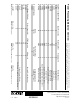
Model
NC-NXS
Hi
Data
Lo
Network
Address
0
8
1
9
2
A
3
B
4
C
5
D
6
E
7
F
0
8
1
9
2
A
3
B
4
C
5
D
6
E
7
F
Model
Name
CKS 100
CKS 200
CKS 400
CKS 800
CKS 800-2
CKS 1200-2
CKS 1600-2
Output Power
@8Ω/Ch.
50W
100W
200W
400W
400W
600W
800W
Crest Audio Inc.
100 Eisenhower Dr.
Paramus, New Jersey 07652 USA
Designed & manufactured in the USA by:
+–
+–
Model
Name
CKV 100
CKV 200
CKV 400
CKV 800
CKV 1600
CKV 2400
Output Power
@70.7V
50W
100W
200W
400W
800W
1200W
CLASS 2 WIRING
MAY BE USED
Output
A
B
+
+
–
–
Signal
Ground
Lift
Jumper
PUSH
Error
AES/EBU
In
SEE INST
R
N-Coder
Data
Port
Ribbon Cable from
Network Module, if fitted
Model
NC-IPN
+
+
Input A
Input B
–
–
7
8
9
5
2
0
1
3
4
6
10
7
8
9
5
2
0
1
3
4
6
10
N-Coder
Data
Port
Level
B
Level
A
SEE INSTRUCTION MANUAL
0
8
1
9
2
A
3
B
4
C
5
D
6
E
7
F
0
8
1
9
2
A
3
B
4
C
5
D
6
E
7
F
Model
Name
CKS 100
CKS 200
CKS 400
CKS 800
CKS 800-2
CKS 1200-2
CKS 1600-2
Output Power
@8Ω/Ch.
50W
100W
200W
400W
400W
600W
800W
Model
NC-NXS
Hi
Data
Lo
Crest Audio Inc.
100 Eisenhower Dr.
Paramus, New Jersey 07652 USA
Designed & manufactured in the USA by:
Network
+–
+–
Address
Model
Name
CKV 100
CKV 200
CKV 400
CKV 800
CKV 1600
CKV 2400
Output Power
@70.7V
50W
100W
200W
400W
800W
1200W
Network Module
If Load Monitoring is
employed, an additional ribbon
cable will be located here.
Input Module