
Instruction manual

Input Processing Module Connections
The CK family of amplifiers come standard with a CC-IPB Input module. Barrier strip input con-
nectors and removable individual channel rotary attenuators are provided. All Input modules have
an internal voltage gain/input sensitivity jumper that is factory-set for X40 gain.
Input barrier strip lug / gauge information
Input barrier strips have a 0.325" (8.3mm) center and 0.270" (6.9mm) lug space. For connecting to
the input barrier strips, a wire gauge between 14 AWG (2.5mm
2
) & 24 AWG (0.25mm
2
), and spade
lugs (Panduit Part No. PNF 18-6LF-C or equivalent) are recommended.
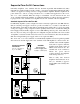
Balanced vs. unbalanced inputs
Barrier strip inputs are ready to accept balanced sig-
nals. For use with an unbalanced source, tie the
inverting (minus) input to ground by installing a
jumper across the appropriate barrier strip terminals.
If the inverting input is left floating, a 6 dB loss in
gain will result.
AES/EBU Input
This XLR jack accepts a standard AES/EBU XLR
plug.
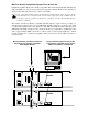
Daisy chaining
Some Input Processing modules have daisy-chained outputs, located on barrier strip terminals.
NC-AES and NC-DSP-D modules have balanced daisy chain outputs.
NC-DSP-A and NC-SEQ modules have unbalanced daisy chain outputs.
NC-MCO and NC-MEQ modules have unbalanced mono HP/LP daisy chain outputs.
The NC-SCO module has unbalanced stereo HP/LP daisy chain outputs.
NC-IPE page input & enable connections
Get information from engineering
Input Processing Module Attenuators
Operation
Channel attenuators (A&B) are used to control signal level. Ideally, the amplifier should be operat-
ed with the controls at 0dB attenuation. When the amplifier is being used in bridged mono mode,
both attenuators must at the same level.
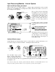
Knob Removal
The attenuator knobs can be removed and replaced with blanking plugs.
The procedure for attenuator knob removal is as follows:
1. With an X-Acto or similar knife, pop off the grey key cap of the attenuator knob. This will reveal
the inside nut.
2. Using needle nose pliers or appropriate size nut driver, loosen and remove the inside nut.
3. Slide the attenuator knob off the shaft.
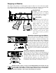
4. Insert a regular screwdriver in the slotted end of the shaft, and adjust attenuation to desired level.
5. Blanking plugs may now be inserted in the attenuator holes.
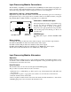
Input Barrier Strip
Level
B
Level
A
Input A
Input B
+
+
–
–
7
8
9
5
2
0
1
3
4
6
10
7
8
9
5
2
0
1
3
4
6
10
Model
CC-IPB
SEE INSTRUCTION MANUAL
Input Level
Attenuators