CDVS-4200 Series Embedded DVR Setup And Users Manual Crest Electronics, Inc. Version 08.12.
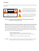
Caution This installation should be performed by qualified service personnel and should conform to all Federal State and local laws. The lightning flash with arrowhead symbol, within an equilateral triangle is intended to alert the user to the presence of uninsulated dangerous voltage within the product’s enclosure that may be of sufficient magnitude to constitute a risk of electric shock to persons. CAUTION RISK OF ELECTRIC SHOCK DO NOT OPEN CAUTION: TO REDUCE THE RISK OF ELECTRIC SHOCK.
Important Safeguards Warning 1. Turn off power to the unit prior to changing the battery. 2. Check the polarity of the lithium battery while changing. 3. When changing battery use the same type as original or similar type recommended by your vendor. 4. Dispose of old battery in accordance with the manufacturer of the battery. General Warning Warning 1. Use the power cord which is supplied or recommended by the manufacturer. Failure to do so could cause a fire. 2.
Caution 1. Use the power cord and power transformer supplied by the manufacturer or one recommended by the manufacturer. 2. The internal fan rotates at high speed and may cause injury. 3. Do not drop, give unit strong vibration or shock to the product; doing so will cause malfunction. 4. Slots and openings in the front and back of the cabinet are provided for ventilation, to ensure reliable operation of the unit, and to protect it from overheating. These openings must not be blocked or covered.
Table of Contents Caution.................................................................................................................................................................i Safeguards.............................................................................................................................................................ii Cautions.................................................................................................................................................
Device (Camera) Audio............................................................................................................................7-12 Device (Alarm) .........................................................................................................................................7-13 Device (Alarm) Sensor..............................................................................................................................
Contents Please check the package for the following items. If any items are missing please contact your dealer. • 4200 DVR • Power cord • Remote controller • USB Mouse • Utilities Disk • Looping Output Cable (16 channel only) Remote Controller CDVS-4200 Utilities CD Looping Output Cable 16 channel only.
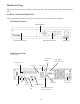
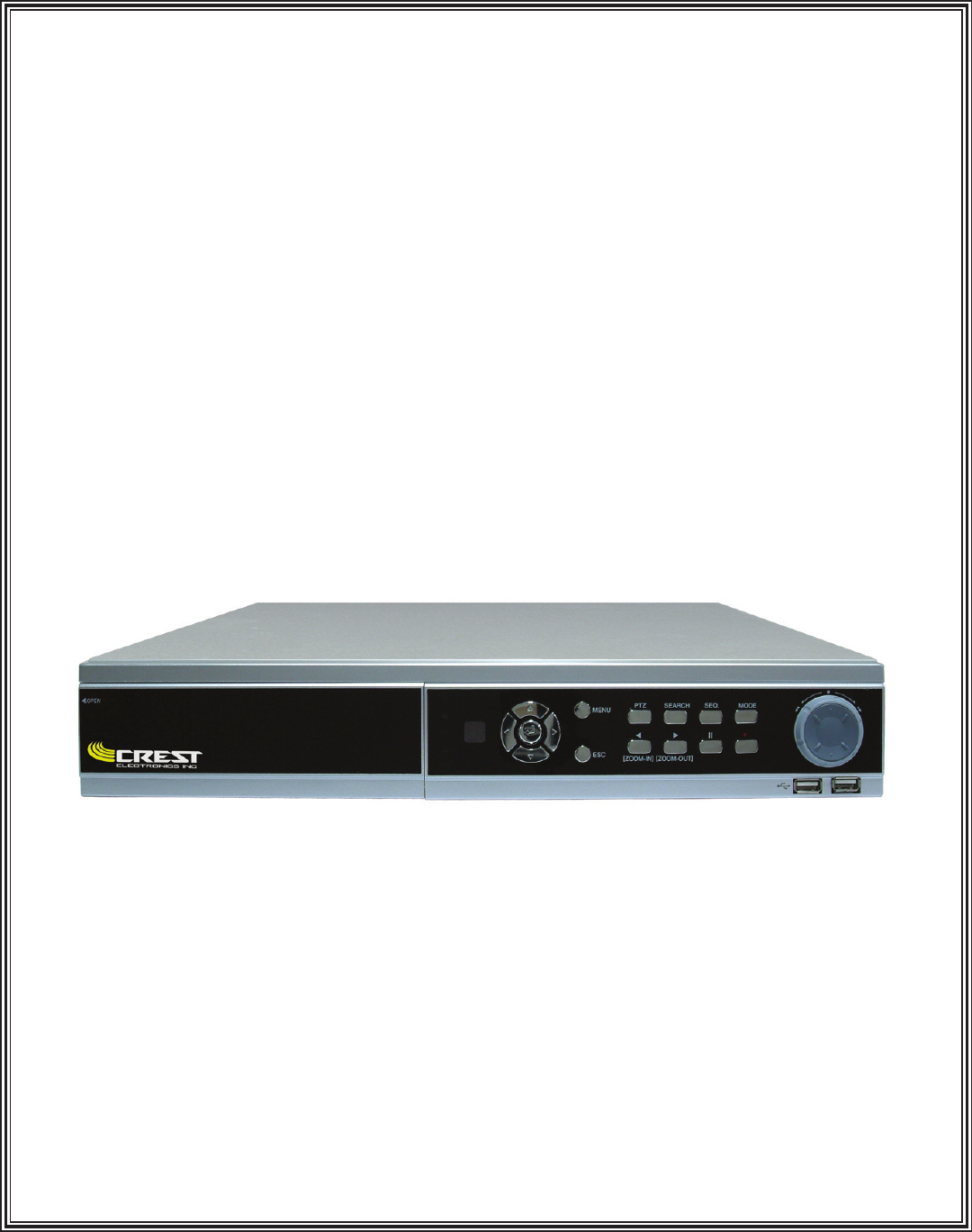
Hardware Setup This section describes the front and back connections of the CDVS-4216H,4216L, 4208, 4204 Embedded DVR. 4216H 16 Channel Embedded DVR The images that follow show the hardware connections for the 16 channel embedded DVR. Front Panel Controls On/Off Button DVD/CD-RW Drive Front Panel Controls USB Ports Back Panel Controls (4216H shown) Spot monitor Output Video Inputs 1 - 16 Audio Out Mon.
4216L 16 Channel Embedded DVR The images that follow show the hardware connections for the 16 channel embedded DVR. Front Panel Controls On/Off Button DVD/CD-RW Drive Front Panel Controls USB Ports Back Panel Controls (4216L shown) Spot monitor Output Video Inputs 1 - 16 Audio Out Mon.
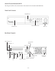
4208 8 Channel Embedded DVR The images that follow show the hardware connections for the 8 channel embedded DVR. Front Panel Controls On/Off Button Front Panel Controls CD-RW Drive USB Ports Back Panel Controls Video Outputs 1 - 8 Video Inputs 1 - 8 Spot monitor Output Audio Input S-Video Two way USB Audio Out Audio In Out ports Sensor/Relay/Ground/ NTSC/ VGA 422/485 connections PAL Mon.
4204 4 Channel Embedded DVR The images that follow show the hardware connections for the 4 channel embedded DVR. Front Panel Controls On/Off Button Front Panel Controls CD-RW Drive USB Ports Back Panel Controls Video Outputs 1 - 4 Video Inputs 1 - 4 Audio Input Spot monitor Output S-Video Two way Audio Out Audio In Out LAN connection NTSC/ VGA Sensor/Relay/Ground/ PAL Mon.
The 4216H DVR Data Input and Output Terminal Pin Assignment The drawing below shows the pin assignments for the sensors, relays and PTZ RS 485 data port for the 4216H. Please see next page for the pin assignments for the 4204, 4208, 4216L. 32 31 30 29 28 27 26 25 24 23 22 1 Pin No.
The 4204, 4208, 4216L DVR Data Input and Output Terminal Pin Assignment The drawing below shows the pin assignments for the sensors, relays and PTZ RS 485 data port for the 4204, 4208, 4216L. Please see previous page for the pin assignments for the 4216H. Pin No.
Description of Hardware Connections Video Input BNCs Use the BNC connection to connect the BNC cable from the camera to the DVR. Audio Output Use this connection to connect to (optional) external speakers. Spot Monitor Output Use this port to connect an external (optional) spot monitor to the DVR. Audio Inputs These ports are used to connect external (optional) microphones to the DVR. Looping Output Connection Use this connection to connect the looping octopus cable.
Powering Up The DVR For The First Time The default settings of the 4200 series DVR will allow the DVR to begin recording in continuous mode after all the hardware has been installed and the unit is powered on. The steps below will walk you through setting the date and time for your unit. After making all connections to the DVR, turn on the DVR by pushing the on/off button located on the front panel of the DVR.
Setting The Time Zone The time zone can be set for the area in which you live by following the directions below. To get to the time setup screen right click the mouse button or push the menu button on the front panel. This will bring up the menu popup screen select Main Menu. From the System Menu click the Time Setup button as shown in image below. Click Main Menu Click Time Setup From the Time Setup menu select the DST tab to setup daylight savings time.
Daylight Savings Start and End date for the US. 2009 2010 2011 2012 2013 2014 Start March 8 2:00am Start March 14 2:00am Start March 13 2:00am Start March 11 2:00am Start March 10 2:00am Start March 9 2:00am End Nov. 1 2:00am End Nov. 7 2:00am End Nov. 6 2:00am End Nov. 4 2:00am End Nov. 3 2:00am End Nov. 2 2:00am Setting the Time From the Time Setup Menu shown below click the Time Setup tab. Set the Time Zone, Date Format, Date and Time for your particular area.
Different Time Zones Around the World The chart below shows the amount of time + or - from Greenwich Mean Time. This will help you in setting your particular time zone.
(GMT + 05:00) Ekaterinburg (GMT + 05:00) Islamabad, Karachi, Tashkent (GMT + 05:45) Kathmandu (GMT + 06:00) Almaty, Novosibirsk (GMT + 06:00) Astana, Dhaka (GMT + 06:00) Sri Jayawardenepura (GMT + 06:30) Rangoon (GMT + 07:00) Bangkok, Hanoi, Jakarta (GMT + 07:00) Krasnoyarsk (GMT + 08:00) Beijing, Chongqing, Hong Kong, Urumqi (GMT + 08:00) Irkutsk, Ulaan Bataar (GMT + 08:00) Kuala Lumpur, Singapore (GMT + 08:00) Perth (GMT + 08:00) Taipei (GMT + 09:00) Osaka, Sapporo, Tokyo (GMT + 09:00) Seoul (GMT + 09:00)
Default Settings The following is a listing of the default settings for the DVR.
Controlling the DVR There are three ways to control the DVR; using the USB mouse, using the remote controller, or using the front panel. This section will provide you an overview of the functions used with the remote controller and the front panel. Using The Remote Controller. The remote controller can be used to control the various functions of the DVR. The controller and DVR come preset to ID 0. If more than one DVR is used at the same location you can set a different ID for each DVR and controller.
Setting the ID on the remote controller The controller ID can be set from 00-99; This is useful when there are two DVR in close proximity to each other. The two controllers can be set to use two different ID so they will not interfere with each other. The controller ID must be set in both the remote controller and the DVR. To set the ID on the controller, follow the instructions below: 1) Push and hold the ID button until the red light stays on.
3) Click Main Menu to enter the System Menu. (See image below). Select Information Menu System Menu 4) Click the Information Menu bar, the System Information screen appears (see below). Click the up or down arrows to move the ID number System Information Menu 5) Click the up or down arrows to change the setting for the controller ID. After changing the ID, click the OK button to save the change. Click OK at the system menu to get to the main screen. 6) The remote controller is now ready for use.
Front Panel Functions The image below details the functions of the front panel. These functions are the same for the remote controller. 2 3 4 5 6 7 8 9 10 11 12 13 14 1 1) Power button - Turns the unit on and off. 2) Enter and cursor movement control - Moves the on screen cursor in the direction of the arrow. Pressing the center button selects desired function. 3) Menu button - When pressed this button will bring up the on screen pop up menu.
Helpful Hints Using the Front Panel / Remote Use the directional controls on the remote controller and front panel to control the movement of the cursor on screen. Press the left, right, up or down arrows to move the cursor. To select an option, move the cursor over the option and push the enter button. Use the left, right, up, down arrows to move the on screen cursor. Press enter to select option.
Screen Display When the system boots it will display the 16 camera display. The user can choose from several different screen displays. To change screen display from the front panel, push the mode button. To use the remote, push the mode button. Keep pushing the mode button to display the different screen displays. To use the mouse, move the mouse button to the bottom of the screen and the screen display bar will appear. See image below.
2 1 2 1 3 3 4 4 Four Camera Display 5 6 Six Camera Display 2 1 2 3 4 5 6 7 8 9 3 1 4 5 6 7 8 Eight Camera Display 1 Nine Camera Display 2 2 3 4 6 5 8 1 3 4 5 6 7 7 8 9 10 10 Ten Camera Display 9 11 12 Thirteen Camera Display 5-2 13
Camera Sequence The DVR will sequence through the different screen layouts as shown below. To activate screen sequence function from the front panel, push the mode button until you have the desired screen layout. Next, push the SEQ button on the front panel, this will activate the sequence function. To turn off the sequence function, press the front panel SEQ button again. To activate the sequence function with the remote control, click the mode button until the desired screen layout is displayed.
Four Camera Display Screen Rotation 1 2 5 6 3 4 7 8 13 14 9 10 15 16 11 12 Displays the first four cameras then next four until it comes back to 1st four.
10 16 9 15 11 12 13 1 14 2 3 4 6 12 5 11 7 8 9 13 10 14 15 16 Eight Camera Display Screen Rotation 2 10 3 1 11 9 4 5 6 7 12 8 13 5-5 14 15 16
Nine Camera Display Screen Rotation 1 2 3 10 11 12 3 4 5 4 5 6 13 14 15 6 7 8 7 8 9 16 1 2 9 10 11 12 13 14 5 6 7 14 15 16 15 16 1 8 9 10 1 2 3 2 3 4 11 12 13 4 5 6 7 8 9 16 1 2 9 10 11 10 11 12 3 4 5 12 13 14 13 14 15 6 7 8 15 16 1 2 3 4 11 12 13 4 5 6 5 6 7 14 15 16 7 8 9 8 9 10 1 2 3 10 11 12 Continued on next page 5-6
13 14 15 6 7 8 15 16 1 16 1 2 9 10 11 2 3 4 3 4 5 12 13 14 5 6 7 8 9 10 11 12 13 14 15 16 12 5 Ten Camera Display Screen Rotation 1 2 11 6 3 4 5 6 13 14 15 16 7 8 9 10 7 8 9 10 1 2 3 4 11 12 13 14 15 16 9 10 3 4 1 2 3 4 11 12 13 14 5 6 7 8 5 6 7 8 15 16 1 2 9 10 11 12 Continued on next page 5-7
13 14 7 8 15 16 1 2 9 10 11 12 3 4 5 6 13 14 15 16 16 1 2 12 5 16 Thirteen Camera Display Screen Rotation 2 3 4 6 5 15 8 3 1 13 9 4 15 2 14 7 14 11 6 1 3 10 11 12 13 7 8 9 10 4 5 6 7 9 10 11 12 6 7 8 9 3 4 5 6 15 10 12 7 13 8 9 5 14 16 11 2 13 8 10 1 2 3 4 14 15 16 1 11 12 13 14 16 1 2 3 13 14 15 16 10 11 12 13 6 1 3 14 4 15 5 8 9 16 12 10 7 2 11 5 6 9 7 4 15 8 2 1 3 4 5 Continue
7 8 9 11 10 4 13 8 5 6 6 7 1 10 5 2 14 9 4 7 3 12 3 16 11 6 8 15 16 1 2 12 13 14 15 9 10 11 12 14 15 16 1 11 12 13 14 8 9 10 11 4 15 1 10 2 13 3 5 16 3 6 7 8 9 5 6 7 8 9 4 11 4 10 13 12 14 14 10 15 16 5-9 7 5 2 13 6 16 15 1 2 3
Overview of the Main Screen The image below shows the main screen and details the features of the main screen. Motion detected will turn red if recording by motion Camera title FPS recording Current date and time Red dot means recording in continuous mode HDD recording level. Red indicates full System temperature Red indicates that system is overheating Symbols A red dot in the upper right corner of the image indicates that the DVR is recording video.
A The symbol A will display in red when the unit has been set up to record audio. (This will display even if there is no microphone connected to the DVR). The alarm symbol will appear yellow when there is an alarm condition, but the DVR is set to record in motion or continuous mode. The alarm symbol will display blue when the DVR is set up for alarm recording and there is no alarm condition. When there is an alarm condition it will turn red.
Main System Menu Pop Up Box Overview of Pop Up Menu The options on the main menu pop up box allow the user to set properties for the DVR, search recorded video, back up recorded video, turn on the digital PTZ function, freeze the live screen, and activate the PTZ camera functions. To bring up the main menu, right click the mouse button, click the menu button on the front panel or press the menu button on the remote controller. The main menu pop up window is shown below.
Setting Up The DVR This section will describe how to set up the different functions of the embedded DVR. To bring up the Setup Menu, right click the mouse button. Next, click the Main Menu button. See images below. Right click the mouse button or press the menu button on the front panel or on the remote controller. The main menu appears.
The System Menu The System Menu functions are explained in detail in this section. System (Information) screen System Information Screen • DVR Title - Click in the white box to change the name of the DVR. Use the virtual keyboard to enter a new name. Virtual keyboard will appear once you click in the white box. • Controller ID - Use this box to select a new controller ID. (See earlier section 4-2 on how to change ID on remote controller). Available numbers are 00 -99.
System (Time Setup) Screen System Time Setup Time Setup • Time Zone - This will set the time zone for the local area the DVR is located. It is in Greenwich mean time. Please see page 3-4 for listing of the different areas of the World. • Date Format - This allows the user to control the format of the date and time displays on the DVR. The choices are; YY-MM-DD, MM-DD-YY, and DD-MM-YY. • Date - This sets the DVR to the current date.
Holiday Setup • The DVR allows the user to create special Holidays. When a holiday is created, the DVR will follow the Recording Schedule set up on the Holiday line of the recording schedule. Image below shows the Holiday setup screen. Holiday System Setup During a holiday the system will use the Holiday line for recording Time Sync. The Time Sync function allows the DVR to sync its time with a network time server.
System (Disk Manager) The disk manager screen contains information about the drives connected to your DVR. This includes any USB or CD/DVD drives attached to be used for backup. This screen also allows the user to format the various devices. System Disk Manager Screen. • Check HDD - To check the total HDD size and amount of Disk space free, place a check mark in box beside the drive you want.
System (User Account) The user account screen allows the user to administer users on the system. The Embedded DVR allows for nine user accounts and one administrator account. The image below shows the User Account screen. • User Name - Select user admin or user 1 through 9 • User ID - This is the account the user will use to log into the DVR. • Password - Enter a unique password for the user. Can be no more than 10 characters, alpha numeric only.
System (Covert Cameras) The covert tab in the user setup screen allows the DVR to block camera views based on user. To block a user from viewing a camera, place a check mark beside the camera you want hidden. (see image below) To block a camera from a user, place a check mark beside the camera you want to be hidden.
The Device Menu The Device Menu contains the setup screens for Cameras, audio Alarm and what displays on screen. The image below shows the Device Menu. The device menu Device (Camera) Screen Camera setup allows the user to enable or disable the camera ports. It also allows the user to give the camera a title to identify the camera. Also, this menu allows the user to set the frame rate and image quality per camera. Total available frame rate for each camera is displayed at the bottem of the screen.
To Change a Single Camera: Select the camera to make changes to by clicking with the mouse button, remote controller or front panel. The camera icon will turn yellow. Check the enable box to turn on the camera port. Check pop up box if you want the camera to pop up full screen on event To rename the camera, click in the box. The virtual keyboard will appear. Select camera resolution CIF, 2Cif or D1. To change frame rate, click the up or down arrows.
Device (Camera) PTZ Setup If you have a Pan Tilt Zoom camera, use the PTZ tab in the Device (Camera) menu (see image below). At the present time, the software supports the following PTZ camera protocol: Fine CRR1600, Kalatel KTD312, LG_LPT_A100l, Pelco D, Pelco P, ORX 1000, Samsung SSRX1004, Samsung SCC641, Sungjin, Vicon, and Unitec. Check with the technical support department if your PTZ camera is not on the list as we are adding to our PTZ library.
Device (Camera) Color Control Use the Color Control menu to adjust the color of attached cameras. Click the color control button, the color control screen appears. Select the camera you want to adjust. Move the slider bar to adjust Brightness contrast or hue. Click OK. After adjusting all cameras you will then be returned to the camera device main menu. See image below.
Device (Alarm) The system allows for alarming by sensor, motion, video loss, and system displays such as temperature indicator and hard disk usage. The Embedded DVR provides for alarm inputs (sensors) and relay outputs (relays). The 4216H has 16 sensors and 4 relays, the 4216L has 16 sensors and 1 relay, 4208 channel has 8 sensors and 1 relay, and the 4 channel provides 4 sensors and 1 relay. The system can be set up to detect motion and create an alarm event.
The Embeded DVR Data Input and Output Terminal Pin Assignment The drawing below shows the pin assignments for the sensors, relays and PTZ RS 485 data port for the 4216H. Please see next page for the pin assignments for the 4204, 4208, 4216L. 32 31 30 29 28 27 26 25 24 23 22 21 20 19 18 1 2 3 4 7 9 10 12 13 14 Pin No.
Pin No. Pin 1 Pin 2 Pin 3 Pin 4 Pin 5 Pin 6 Pin 7 Pin 8 Pin 9 Pin 10 Pin 11 Pin 12 Pin 13 Signal Name Sensor In 13 Sensor In 12 Sensor In 11 Sensor In 10 Sensor In 9 Sensor In 8 Sensor In 7 Sensor In 6 Sensor In 5 Sensor In 4 Sensor In 3 Sensor In 2 Sensor In 1 Pin No.
Device (Alarm) Motion The embedded DVR can be set up to activate relays when the system detects motion. To use motion to activate a relay, click the motion tab from the Device (Alarm) window. When the motion alarm window appears, click the camera you want to activate the relay (icon will turn gold). Click the enable check box, choose which relay to link to this camera. Set the dwell time for the relay signal. When motion is detected the system will send a relay signal to the specified relay.
Device (Alarm) System The system monitors the internal temperature of the DVR and the amount of used disk space. This function allows the user to set the minimum temperature that when reached will warn the user by graphic display and turn on additional cooling fans. The temperature display will change from blue to red when the internal temperature exceeds this minimum. It is very important to keep the system cool, failure to do so could result in damage to the DVR.
Device (Sequence) System Use the Screen Sequence menu to set the camera sequence of the main monitor and the spot monitor. Only checked cameras will display on the main monitor when in sequence mode. Only cameras that are checked will be displayed when using spot monitor.
The Record Menu The record menu controls the resolution and record mode for the DVR. The record menu consist of two menus - Setup and Schedule. Setup controls the resolution, recording mode (continuous or schedule), pre alarm, post alarm, HDD overwrite and the motion area setup screen. The schedule menu allows for setting of a daily and holiday recording schedule. To get to the Record Menu, click the Record button from the main menu, the Record screen appears.
Record (Setup) Click the Setup button from the main record menu, the Record (Setup) window appears. Set recording mode Turn on/off Pre Alarm Turn on/off Post alarm Limit Days Set motion area grid and sensitivity Overwrite HDD files when full • Mode - There are two types of recording modes - continuous or schedule. • Pre Alarm - Pre alarm will capture 200 frames of video before an alarm event. The options are on or off. • Post alarm - Post alarm will capture 200 frames after alarm.
Motion Area Setup Window The motion area setup window allows the user to highlight areas of the image to detect motion. It also allows for changing the sensitivity of motion detection. To use, click the Motion Area Setup button. Select a camera to change the motion grid. The entire image is selected to detect motion by default. To unselect an area, right click the mouse, or use the menu button on the remote controller or front panel.
Record (Schedule) The DVR allows for continuous recording or recording by schedule. To record continuously, just select the continuous mode in the Record (Setup) window. The Record (Schedule) window allows the user to set each camera by a schedule. The schedule is broken down by individual camera, day, and hour. There is even a special holiday period which can be set to record differently than the normal recording mode. To set the recording mode, click the Schedule button on the main Record window.
Schedule record window The image above shows the Schedule record window. To set the recording mode for a particular camera, click the camera, it will change to a gold color. If you want the same recording mode and schedule for multiple cameras, use the right mouse button to select the cameras. They will all change to gold color. Place a check mark in the recording mode you want. Select the hour and day you want the camera to record in this mode.
Network The DVR allows remote connection through TCP/IP connection. The networking menu contains six sub menus - IP Setup, E-mail Notification, and web Server Setup. To open the Networking Menu, click the Network button on the main setup screen. See image below. IP setup E-Mail Notification Web Server Setup DDNS Setup Click Network Tab Event Notification Bandwidth Limit Network port Network (IP Setup) To set the DVR up on a IP network, click the IP Setup button.
TCP/IP Information When using a Static IP, you need to provide the DVR with the IP address, subnet mask, Gateway, and DNS number. These must be obtained from your network administrator or your internet service provider. If you are using DHCP or xDSL connection, this information will be obtained automatically by the system. The image below shows the TCP/IP information.
Network (Web Server Setup) The DVR has the ability to act as a web server for remote connection via internet web browser. This menu will set up the DVR to act as a web server. Click the enable box to turn on the web server function. Enter a port number for the web server (default is port 80). Now the DVR will act as a web server. All controls will be downloaded when the user connects to the DVR the first time.
Network (Event Notification) Event Notification transmits information (motion detection, etc) to the registered IP address (of the computer running the remote software) when an event occurs. The system allows for you to send this information to 10 different remote systems. Click the use box then enter the static IP address of the computer running the remote software (for example 192.168.1.8) in the target address box. Save the changes by clicking OK button.
Event Menu The event menu contains three logs for the user to review. The three logs are Sensor, Video Loss, and System. To view the different logs, click on the desired log and the log will be displayed.
Searching Recorded Video To search recorded video, right click the mouse button or press menu on the remote controller or front panel to bring up the main menu (see image below). Click search button to begin search mode. Search Menu The main search menu consist of three sub menus - Calendar search, Motion search, Event Search. Calendar search lets the user search video by date and time regardless of the record mode. Motion search allows the user to search only the video that was recorded in motion mode.
Event (Calendar Search) The Calendar search window allows the user to search for recorded video by date and time. The search screen consist of the selected date and time display, a calendar showing the days that have recorded video and a hour and minute bar. The selected date and time display reflects the currently selected date and time. As the user changes the selected day or hour and minute this display will update to reflect the changes.
Search (Motion Search) Motion search allows the user to search for video only recorded when there was motion. This is useful when the system has been set up to record in both sensor + motion mode. The Motion search window allows the user to search for video recorded in motion mode by date and time. The search screen consist of the selected date and time display, a calendar showing the days that have video recorded in motion mode and an hour and minute bar.
Search (Event Search) The event search screen allows the user to search video only recorded in sensor mode. This is useful when the system has been set up to record in both sensor + motion mode. The Event search window allows the user to search for video recorded in sensor mode by date and time. The search screen consist of the selected date and time display, a calendar showing the days that have video recorded in sensor mode and an hour and minute bar.
Playback Screen Functions After selecting the search method, click OK, and the system changes to the playback screen. There are several playback functions to help the user review video. The section below shows the functions using the mouse, remote controller, and front panel. Using The Mouse to control Playback The mouse can be used to control stopping, starting, direction, speed, and frame by frame playback.
Search Playback Screen Popup Menu While in the playback screen click the right mouse button to show the popup menu. From this menu you can select: Go To Main: Move to the main search screen. Go To Live: Close the search screen and moveto the live view scren. Go To Backup: Change to backup mode and move to the backup screen. Digital PTZ On: Activates the digital PTZ function and the selected channel is changed to full screen.
Using the Remote Controller to Control Playback The remote controller can be used to control the playback functions. The images below show the various buttons and describe the functions they control. Controls the on screen cursor movement Menu button used to bring up playback menu Push search button to bring up search menu Use to control the direction (forward or reverse) and speed of playback. Play reverse normal speed.
Backing Up Recorded Video The DVR allows the user to backup recorded video to a CD, DVD or USB disk drive. Insert backup mediathen from live view mode, begin backup by right clicking the mouse button. When the main pop up menu appears select Backup. The backup window is shown below.
Replay of Backup Files As stated earlier backup files can be either VDB or AVI files. VDB files require a program called Simpleview that was downloaded when the backup was made. AVI files require windows media player with DIVX codec installed. Replay using SimpleView Program After loading you backup media (CD,DVD or USB memory stick) to a PC and go to the directory that contained the backup files. You will see a folder similar to the graphic below. Double click the simpleview folder.
After choosing the directory the simpleview program will display the date or dates you backed up. See picture below. Select the date hour min and second you want simpleview to start playback. You do this by first clicking on the date then hour then min and finally the second that you want playback to start. Playback will start automatically after choosing the second. See screen below. Select date hour min. sec.
Digital PTZ The digital PTZ function allows the user to enlarge a live or recorded image. As the image is zoomed parts of the screen that were visible cannot be seen. When this happens the user is able to move the screen in the same manner as a PTZ camera enabling the user to view the hidden parts of the image. To use digital PTZ, click the image you want to enlarge (this will select the image), Right click the mouse and select Digital PTZ from the pop up menu.
Dynamic PTZ To set up the PTZ camera see the section on setting up a PTZ camera. The DVR can control a PTZ camera with the mouse, remote controller or front panel. To place the DVR in PTZ mode right click the screen with the mouse to bring up the pop up menu. Push the PTZ button on the front panel or Remote controller. A controller icon will appear in all images that have been set up as PTZ cameras.
Appendix DDNS Registration The following is an example of how to register with one of the three supported DDNS servers. This example will use the www.ddnsin.com server. To begin the registration process you will need to go to a computer with internet access. From that computer launch Internet explorer and input www.ddnsin.com Click “New User Signup” From the DDNSIN.COM main page click New User Signup. Enter UserID, Password and Confirm Password, Then click Submit to complete registration.
After entering in all information click “Submit to complete registration. You will be taken to the user information screen as shown below. Setting Up Client Software Using DDNS Start the crest remote surreillance software. Login to the program and click the setup icon. This will open the site registration window as shown below. Enter the DDNS domain name you registered on the DDNS server in the IP box. In our example we used an ID of abcd so we enter abcd.ddnsin.com where we normally enter an IP address.
Exit the setup screen, in the site connection box click the DVR that you added to the site registration in this case “school” and click connect button. If all information is correct in site registration you will be connected to the DVR. Highlight registered site and click connect.
EL-4000 Relay Characteristics 1. Coil Ratings Rated voltage 3 VDC Rated current 50 mA Coil resistance 60 W Coil inductance: Armature OFF 0.05 (H) (Ref. value): Armature ON 0.11 Must operate voltage 80% max. of rated voltage Must release voltage 10% min. of rated voltage Max. Voltage 200% of rated voltage at 23°C Power consumption Approx. 150 mW 2. Contact Ratings Load Resistive load (cosf = 1) Rated load 0.5 A at 125 VAC; 1 A at 24 VDC Contact material Ag + Au-clad Rated carry current 2 A Max.
Maximum number of words allowed in the input box Input Component DVR Title Time Server User ID Password Camera Title XDSL ID XDSL PWD IP MASK GW DNS MAC Receiver Sender SMTP Server Account Password WEB Port DDNS ID DDNS PSWD Target Address Network Port Location SYSTEM -> Information SYSTEM -> Time Setup -> Time Sync SYSTEM -> USER ACCOUNT SYSTEM -> USER ACCOUNT DEVICE - > Camera NETWORK -> IP Setup NETWORK -> IP Setup NETWORK -> IP Setup NETWORK -> IP Setup NETWORK -> IP Setup NETWORK -> IP Setup NETWORK -