
User's Manual

Copyright Crescend Technologies 7 Rev O
Warning: Be sure that the signal frequency is in the range 403 – 470 MHz!
5. Turn off RF input signal. The fan should continue running, but turn off after approximately 6-12
seconds.
4. PRINCIPLES OF OPERATION
4.1. INTRODUCTION
This section contains principles of operation of the RF Power Amplifier.
4.2. RF INPUT SIGNAL
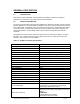
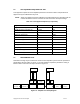
The amplifiers are set at the factory to work over different input power ranges. The available
range of inputs ranges may be found in Table 1-2.
4.3. RF OUTPUT LOAD
The load impedance should be as good as possible (VSWR <1.2:1) in the working band for good
power transfer to the load and maximum amplifier efficiency.
4.4. FUNCTIONAL DESCRIPTION
The amplifier is a single channel CW amplifier that operates over the UHF frequency range. The
amplifier specifications are listed in Tables 1-1 and 1-2.
4.4.1. MAIN RF PATH
The typical main RF path consists of an input attenuator, driver, splitter, final stage(s), combiner,
rf detectors and harmonic filter. The circuitry becomes active upon the sensing of rf input power.
This occurs when rf input reaches approximately 3 dB below the low end of the input power
range. This keeps standby current at a minimum (< 20 mA) when rf input is not present (or is
below the turn on level).
4.4.2. LOOP CONTROL
The loop control circuitry includes circuitry to works to maintain a constant output power versus
variations in DC voltage, rf input power, frequency and load. A coupled detector at the output
monitors the final RF output level and generates a DC voltage proportional to the RF output
level. This voltage is fed back to the controller. The circuitry compares this voltage to a
reference voltage and varies the gain of the amplifier to maintain a constant output.
4.4.3. VSWR PROTECTION
Reflected power is detected at the output of the amplifier and compared to forward power.
When reflected power reaches an equivalent VSWR of approximately 3.5:1, the amplifier output
is reduced to protect the finals and the front panel HIGH VSWR LED activates. The higher the
load VSWR, the more the output power is reduced.
4.4.4. THERMAL PROTECTION
The heat sink temperature is monitored with a thermostat. When the heat sink temperature
reaches an unsafe level, the output power of the amplifier is reduced by approximately 50%.
This keeps the channel on the air while still providing some short term protection until the
customer can address the underlying cooling issue.
4.5. AMPLIFIER COOLING
The amplifier is cooled with forced air over a large heat sink. It is important to keep a minimum
clearance of 3 inches behind the amplifier and allow the coolest air possible to circulate through
the fan.