Crescent d TECHNOLOGIES ISG 8001 Registered Firm INSTALLATION AND SERVICE MANUAL C5 SERIES CONTINUOUS DUTY POWER AMPLIFIER February 9, 2007 Rev B Crescendo Technologies Tel: 847 908 5400 920 E. State Parkway Fax: 847 908 5408 Hamburger, IL 60173 Email: Web Site: www.CrescendTech.
Par. 4.4.1 44.2 4.43 44.
Par. 6.3.1 8.3.
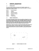
1. GENERAL DESCRIPTION 1.1. INTRODUCTION This manual contains information and procedures for installation, operation, and maintenance of Crescendo's C5 Series Continuous Duty Power Amplifier. The manual is organized into six sections as follows: Section 1. General Description Section 2. Installation Section 3. Operating Instructions Section 4. Principles of Operation Section 5. Maintenance Section 6.
Figure 1-2. C5 Series Amplifier, Rear View 1.3. FUNCTIONAL AND PHYSICAL SPECIFICATIONS Functional and physical specifications for the C5 Series amplifiers are listed in Tables 1-1 and 1-2. 1.4. EQUIPMENT CHANGES Crescendo Technologies, Inc. reserves the right to make minor changes without notice, including, but not necessarily limited to, component substitution and circuitry changes.
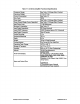
Table 1-1. C5 Series Amplifier Functional Specifications Frequency Range: Ses Table 1-2 (Range Set at Factory) Operating Voltage: +13.8 20.7 Vdc Current Consumption: See Table 1-2 Duty Cycle: 100% Power Input: See Table 1-2 {Range Set at Factory} Power Output {Single Carrier Operation): See Table 1-2 {Range Set at Factory) Input Return Loss: -10 dB (Maximum) Spurious & Harmonics! See Table 1-2 Input/Output Impedance: 50 Ohms {Nominal) Front Panel Display: Load VB Tolerance: SWERVE Protected above 2.
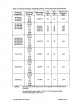
Table 1-2. Frequency Ranges, Outputting Power, Current, Spurious and Harmonics Frequency Range (MHz) input Power Range {(W) Rated Output Power (W) Typ Current (A) Max Current A) Spurious and Harmonics (dBc) 30-36 (AA) 36-42 (AB) 42.50 (AC) 2-5 5-10 10-20 20-50 100 (P10) 20 23 <-65 136-144 (DA) 144-152 (DB) 152-162 (EA) 162-174 (EB) 0.51 1-2 2-5 5-10 10-20 20-50 80 (P8) 100 (P10) 110 (P11) 150 (P15) =-65 <-65 =67 406-426 (GA) 426-450 (GB) 450-470 (HA) 470-490 (HB) 490-512 (HC) 0.
2. INSTALLATION 21. INTRODUCTION This section contains installation recommendations, unpacking, inspection, and installation instructions for the C5 Series of amplifiers. Carefully read all the material in this section prior to equipment unpacking or installation. Also read and review the operating procedures in Section 3 prior to installing the equipment. it is important that the licensee perform these tasks correctly and in good faith.
24. INSTALLATION INSTRUCTIONS The C5 amplifier is designed for installation in a rack that permits access lo the rear of the rack for connection of DC power, RF, and monitor/control cables. The amplifier must have a minimum of 3 inches of open space behind the rear fan to allow adequate ventilation. To install the amplifier proceed as follows: Install amplifier in equipment rack and secure in place. Connect a 50 ohm antenna cable and load to the RF OUT connector on rear of amplifier.
@ 4 Figure 2-2. C5 Series Amplifier, Rear View Right 2.5. AMPLIFIER SUMMARY ALARM AND POWER CUTBACK CONTROL The summary alarm and cutback control connections are made through separate filtered feed through connectors on the back of the amplifier. Table 2-1, Summary Alarm and Cutback Control Connections PIN | FUNCTION DESCRIPTION CONDITION APPROPRIATE Indicates when: Norma Operation: < 1 VOC |> 10 k Ohm, 1. The output power is low, | Alarm: > 8 VDC (up to Veo) |< 100pF or Summary 1.8 k Ohm ALARM | arm 2.
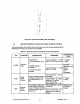
3. GENERAL OPERATING INFORMATION 3.1. INTRODUCTION This section contains operating instructions for the C5 amplifier. 3.2. LOCATION OF STATUS INDICATORS The location and function of the C5 amplifier status indicators and is shown in Figure 3-1 and described in detail in Table 3-1. COCO ~ Figure 3-1, C5 Series Status Indicators, Front Panel Table 3.1, C5 Series Amplifier Status Indicators STATUS LED FUNCTION DC ON Green LED. Rumination indicates DC Power has been applied.
33. INITIAL STARTUP To perform the initial start-up, proceed as follows: Check to ensure that all input and output cables are properly connected and tightened. Note: Use high quality coaxial cable and connectors. Properly install and solder all connectors for reliability. CAUTION: Before applying power, make sure that the input and output of the amplifier are properly terminated in 50 ohms. Do not operate the amplifier without a load attached. Refer to Table 1-2 for input power requirements.
4, PRINCIPLES OF OPERATION 4.1. INTRODUCTION This section contains principles of operation of the C5 Series of RF Power Amplifiers. 4.2. RF INPUT SIGNAL The amplifiers are set at the factory to work over different input power ranges. The available range of inputs for different frequency ranges may be found in Table 1-2. 4.3. RF OUTPUT LOAD The load impedance should be as good as possible (SWERVE in the working band for good power transfer to the load and maximum amplifier efficiency. 4.4.
5. MAINTENANCE 5.1. INTRODUCTION This section contains periodic maintenance and performance test information for the C5 Series. it also contains a list of test equipment required to perform various tests. NOTE: Check your sales order and equipment warranty before attempting to service or repair the unit. Do not break the seals on equipment under warranty or the warranty will be null and void.
5.4, TEST EQUIPMENT REQUIRED FOR TEST Test equipment required to test the amplifier performance is listed in Table 5-2. Equivalent test equipment may be substituted for any item. NOTE: All RF test equipment must be calibrated to 0.05 dB resolution. Any deviation from the nominal attenuation must be accounted for and factored into all output readings. Table 5-2. Test Equipment Required {or equivalent) EQUIPMENT MANUFACTURER MODEL Signal Generator (1) HP.
6. 6.1. TROUBLESHOOTING INTRODUCTION This section contains a list of potential problems and suggested actions to be taken. If the suggested corrective action does not eliminate the problem, please contact your Crescendo factory for further instructions. NOTE: Check your sales order and equipment warranty before attempting to service or repair the unit. Do not break the seals on equipment under warranty or the warranty will be null and void.
6.3. RETURN FOR SERVICE PROCEDURES When returning products to Crescendo, the following procedures will ensure optimum response. 6.3.1. OBTAINING AN RMA A Return Material Authorization (RMA) number must be obtained prior to returning equipment to the factory for service. Please contact our Customer Service Department at 800-872-6233 10 obtain this number. Failure fo obtain this RMA number may result in considerable delays in receiving repair service. 6.3.2.