
Instruction Manual


3 of 5
LPN00848X0001A0_B
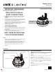
Light Sensor
IR Transmitter
IR Receiver
PIR Sensor
Motion
Indicator
Red LED
PROGRAMMABLE MULTI LEVEL (PML) SENSOR
OPTION
NOTE: The sensor is shipped unattached so it is compatible with
luminaires without or with the reflector accessory. The sensor
assembly should be attached to the heatsink directly when no
reflector accessory is used. The sensor assembly should be
attached to the sensor extension bracket when an accessory
reflector is used.
INSTALL SENSOR WITH NO REFLECTOR
STEP 1:
Secure the molded sensor assembly to the heatsink using 2
Philips head screws provided.
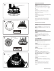
INSTALL SENSOR WITH REFLECTOR
STEP 1:
Secure reflector to luminaire by following reflector accessory
installation steps.
STEP 2:
Secure molded sensor assembly to the sensor extension bracket
using 2 Philips head screws provided. See Figure 6.
STEP 3:
Secure sensor extension bracket and sensor assembly to heatsink
using 2 Philips head screws provided. See Figure 6.
SENSOR DESCRIPTION
The FSP-2X1 is a motion sensor that controls lighting levels based
on occupancy and ambient light.
The sensors use passive infrared (PIR) sensing technology that
reacts to changes in infrared energy (moving body heat) within
the coverage area. Once the sensor stops detecting movement
and the time delay elapses, lights will go from high to low mode
and eventually turn off if it is desired. Sensors must directly “see”
motion of a person or moving object to detect them, so careful
consideration must be given to sensor luminaire placement and
lens selection. Avoid placing the sensor where obstructions may
block the sensor’s line of sight. See Figure 7.
The FSP-2X1 operates on low voltage output of driver, no power
pack is required. It is designed to be installed in indoor and
outdoor environments. Once the device is initially powered up,
the FSP-2X1 will use factory default parameters to operate. If
adjustments are needed, the programming tool must be used.
6
Reflector
Sensor
Extension
Bracket
Heatsinks
Phillips Head
Screws
Sensor
Assembly
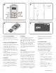
ELECTRICAL CONNECTIONS
STEP 1:
Make the following Electrical Connections:
a. For 120/277V connect the black fixture lead to the voltage
supply or Hot 1 (for 208/240V wiring).
b. For 120/277V connect the white fixture lead to the neutral
supply or Hot 2 (for 208/240V wiring).
c. Connect the green or green/yellow ground lead to the green
wire position of the terminal block.
STEP 2:
For Dimming make the following Electrical Connections using:
NOTE: To access dimming leads follow 0-10V dimming section on
page 3. Class 1 wiring only when dimming leads are used.
d. If 0/1-10V dimming is used connect the violet lead to the
supply positive dimming lead.
e. If 0/1-10V dimming is used, connect the grey or pink lead to
the supply negative dimming lead
LINE
OR HOT 1
GREEN
LINE-BLACK
GROUND-GREEN
NEUTRAL-WHITE
DIM (-) GREY
OR PINK
DIM (+) VIOLET
NEUTRAL
OR HOT 2
VIOLET
GREY
OR PINK
SUPPLY WIRING
(DIMMING OPTIONAL)
LUMINAIRE
7