
Instruction Manual


2 of 5
LPN00848X0001A0_B
each 4 pcs
Glare shield with fixed tabs
3
2
PENDANT MOUNTING
STEP 1:
Remove the hook from the adjustable hook
bracket by loosening the Philips head screw on
the adjustable hook bracket locknut. See Figure
2.
STEP 2:
Insert customer supplied ½” IPS stem into
adjustable hook bracket locknut and tighten
Philips head screw to lock.
STEP 3:
Secure Pendant to structure or junction box using
customer supplied locknuts.
STEP 4:
Attach luminaire cord to customer supplied
junction box and strain relief. Make wiring
connections per the Electrical Connections
section.
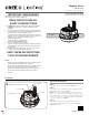
REFLECTOR ACCESSORY
STEP 1:
Secure the reflector to the bottom of the heatsink
by tightening the (4) self-retained Phillips head
screws. See Figure 3.
NOTE: Reflector and Wire Guard cannot be used
together.
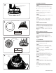
WIRE GUARD ACCESSORY
STEP 1:
Secure the wire guard to the bottom of the
heatsink by tightening the (4) self-retained
Phillips head screws. See Figure 4.
NOTE: Reflector and Wire Guard cannot be used
together.
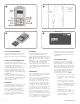
0-10V DIMMING
NOTE: All Luminaires are provided with a 0-10V
dimming driver. Follow the steps below to access
the 0-10V dimming control leads.
STEP 1:
Remove molded driver compartment cover by
removing 2 driver cover screws using 5/32” hex
head bit or allen wrench. See Figure 5.
STEP 2:
Locate Violet and Grey 0-10V dimming leads from
driver and strip leadwire.
STEP 3:
Remove rubber grommet from driver cover,
route dimming cord through cover and connect
dimming cord leads to driver dimming leads. See
Electrical Connections section. See Figure 5.
STEP 4:
Install strain relief on dimming cord
STEP 5:
Reinstall molded driver compartment cover by
securing 2 driver cover screws removed in step 1.
STEP 6:
Attach dimming cord to customer supplied
junction box and strain relief. Make wiring
connections per the Electrical Connections
section.
screws hole
Wire guard
4 screws
4
Phillips Head
Screw
5
Driver
Cover
Screws
Rubber
Grommet