
Specifications
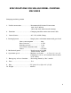
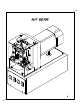
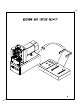
Table Of Contents
- SPA-100 Manual Cover Sheet
- Machine Introduction
- Specifications
- Manual Page
- Diagrams
- Basic Machine Diagram
- Machine and Tester Set-Up
- Machine and Guard Assembly
- Machine Base and Panels Assembly
- Motor and Tool Slide Assembly
- Tool Slide and Punch Holders
- Ram Slide Assembly
- Nest Assembly
- Nest Block Including Nests
- Micro Switch and Nest Stop Assembly
- Punch Holder Assembly (8 Position)
- Cam and Adjustment Assembly
- Test Assembly
- Test Block Assembly - Micro Switch Asseembly
- Controller and Circuits
- Termination Instructions
- Receiving Inspection
- Recommended Spare Tooling and Troubleshooting Tips
- Maintenance for SPA-100
- SPA-100 Parts List
TERMINATION INSTRUCTIONS
These instructions are intended for use with the SPA-100 in conjunction
with Sentinel Connectors modular plugs.
This product comes to you in single assemblies with contacts pre-inserted.
Please refer to product manual for details on determining which of Sentinel’s plugs
will work the best for your application. Any further help may be obtained by
contacting Sentinel direct and obtaining the proper guides.
Once you have determined which combination is best suited, strip the cable
back far enough to allow the individual conductors to be inserted into the plug
while also maintaining the outer jacket positioned under the jacket lock on the
plug. Position the conductors, as desired, and insert them into the plug, making
sure the conductors, as desired, and insert them into the plug, making sure the
conductors are securely positioned against the front of the plastic, to ensure the
contacts penetrate properly.
After preparing cables with connectors, you are ready for termination. If only
one plug is required to be terminated, switch machine to single. If both are
desired, switch the button to double. This will allow you to properly align both
connectors before the ram cycles down. After the ram completes the cycle,
(keeping the plugs positioned in the nests) the test leads will come down, testing
for continuity, shorts and opens. If the tested cable is defective, the tester will
indicate exactly what the defect is. For further instructions on the tester, refer to
the tester manual provided.
Once the cable is completed, a contact height check is necessary to maintain
compliance with FCC, which is .237 +/- .005 from the bottom of the plug base (not
including the tab) to the top of the contacts. This is roughly .023 from the top of
the plug to the contacts at a nominal tolerance.
The tooling can be replaced relatively simply and quickly for short down
time. Each tool can be adjusted individually or as a unit depending on what the
need is.
The machine can be adjusted manually by removing motor guard to obtain
access. Then turn the power off and rotate the fan in the direction desired (the
ram will go up or down depending on the direction fan is turned clockwise or
counter clockwise). Rotate the motor until ram comes down to a plug inserted into
the nest for any adjustment necessary (the contacts in the plug should align with
the contacts that do the driving). After making the adjustment, continue rotating
the motor either way until the ram reaches the top and makes contact with the
micro switch.
7